Knotless anchor for tissue repair

a tissue repair and knotless technology, applied in the field of knotless suture anchors, can solve problems such as difficulty in completing knots and applying appropriate tension

Active Publication Date: 2010-03-16
ARTHREX
View PDF22 Cites 109 Cited by
  • Summary
  • Abstract
  • Description
  • Claims
  • Application Information

AI Technical Summary

Problems solved by technology

Reattachment with suture involves knot-tying, which can present difficulties in completing the knots and applying appropriate tension, especially when operating on small joints such as those in the hand and wrist.

Method used


Image

  • Knotless anchor for tissue repair
  • Knotless anchor for tissue repair
  • Knotless anchor for tissue repair

Examples


Embodiment Construction

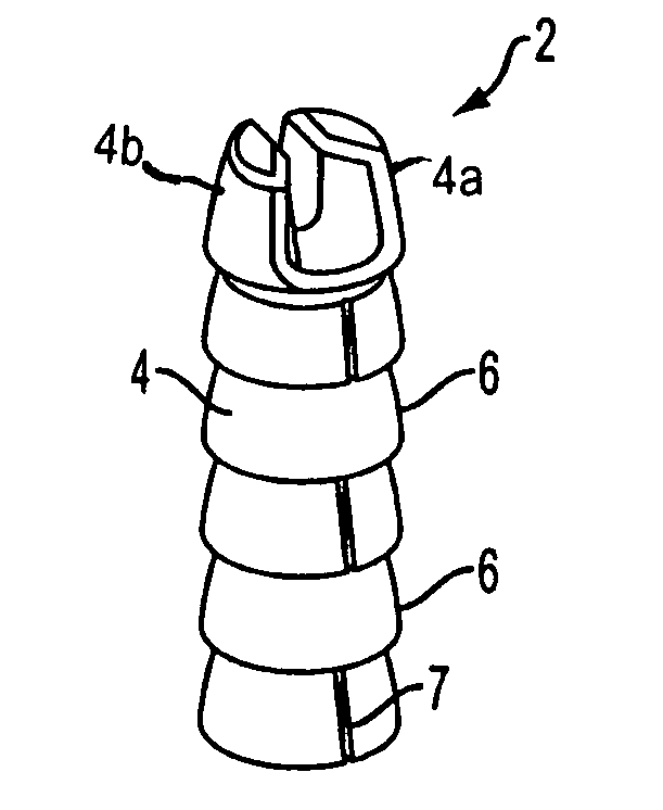
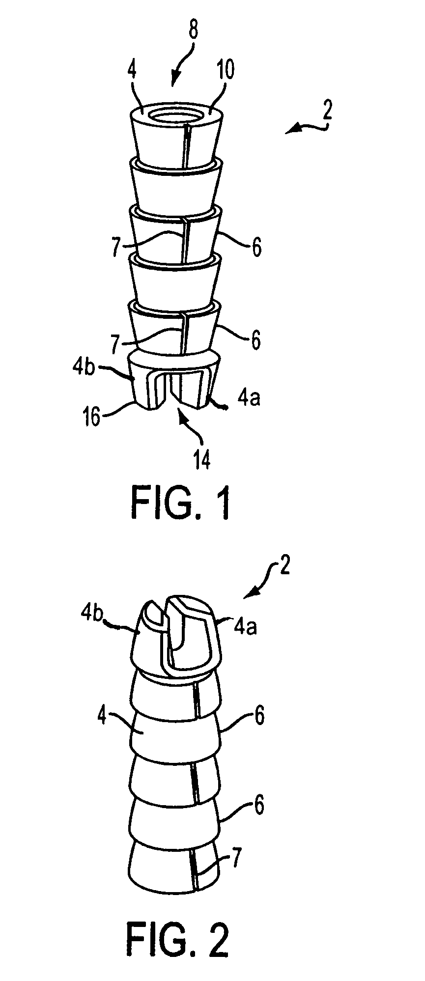
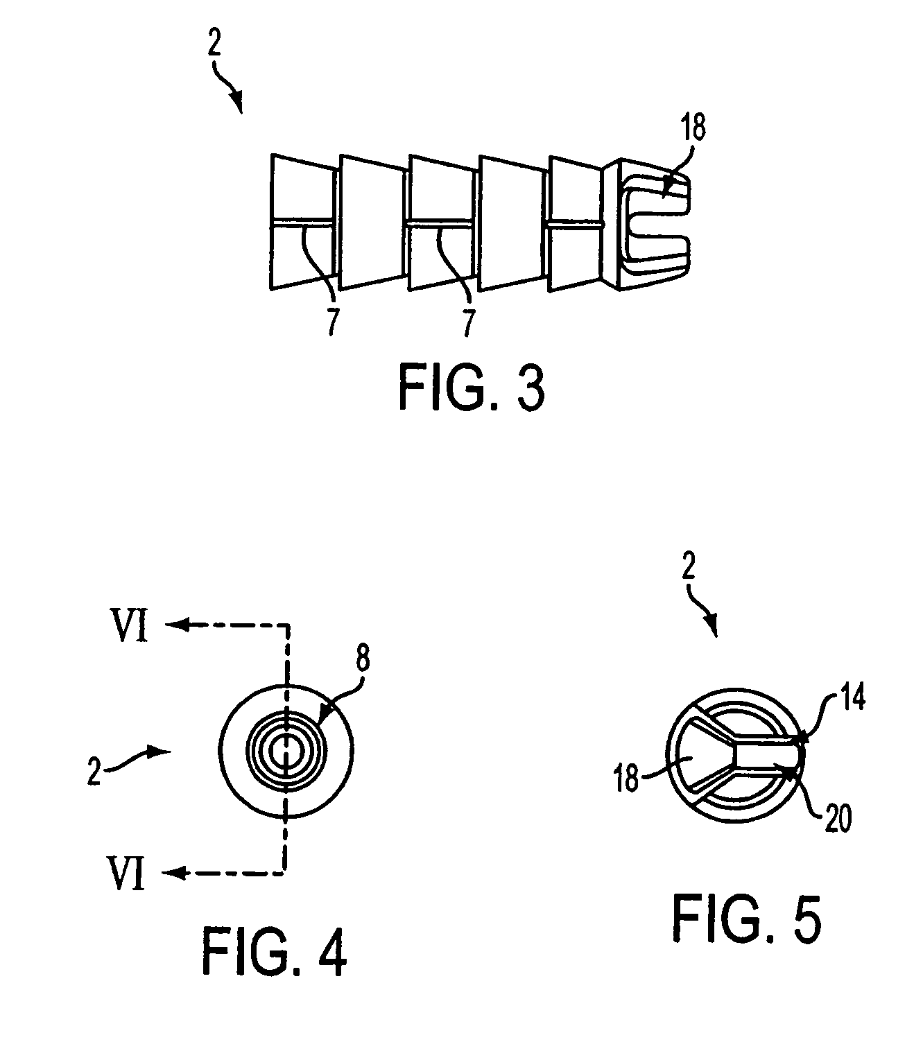
[0021]Referring initially to FIGS. 1-7, a suture anchor 2 according to an exemplary embodiment of the present invention includes a generally cylindrical body 4 having a plurality of circumferential barbs 6. Barb breaks 7 are formed in each barb 6 on alternating sides of the anchor body 4. Suture anchor 2 is made of a bioabsorbable polymer or copolymer, preferably an absorbable polymer such as poly (L-lactide-co-D,L-lactide 70:30).

[0022]An opening 8 is formed in a proximal end 10 of suture anchor 2. Opening 8 provides access to a closed-ended cannulation 12 (FIG. 6) formed inside suture anchor body 4. Sidewalls of the cannulation 12 are smooth. Cannulation 12 narrows toward the closed, distal end and is shaped to accommodate a correspondingly shaped anchor driver described in detail below.

[0023]A slot 14 is formed on a distal end 16 of suture anchor 2. As shown in FIGS. 1 and 2, for example, the slot 14 is defined by opposing members 4a, 4b of the body 4 of suture anchor 2 that exten...


PUM


Abstract

A knotless suture anchor for reattachment of tissue to bone features a barbed body having a Y-shaped slot formed distally for capturing a length of suture. The suture is passed through the tissue to be reattached, and a simple knot formed in the suture is captured in the slot on the suture anchor. The anchor is installed with the captured suture into a pre-formed pilot hole to draw the tissue to the bone.

Description

[0001]This application claims the benefit of U.S. provisional Appl. No. 60 / 509,940 filed Oct. 10, 2003.BACKGROUND OF THE INVENTION[0002]1. Field of the Invention[0003]The present invention relates to apparatus and methods for tissue repair, and more particularly to techniques using knotless suture anchors for reattaching soft tissue to bone.[0004]2. Description of the Related Art[0005]When soft tissues, such as tendons or ligaments, detach from bone, it is often necessary to reconnect the structures surgically. Techniques and devices that have been developed generally involve tying the soft tissue with suture attached to an anchor secured in a hole provided in the bone tissue. Reattachment with suture involves knot-tying, which can present difficulties in completing the knots and applying appropriate tension, especially when operating on small joints such as those in the hand and wrist. It would be beneficial to reattach tissue torn from bone using minimal knot tying.BRIEF SUMMARY O...

Claims


Application Information

Patent Timeline
Patent Type & Authority Patents(United States)
IPC IPC(8): A61B17/04A61B17/84
CPCA61B17/0401A61B2017/0409A61B2017/0412A61B2017/0414A61B2017/0427A61B2017/0438A61F2/0811
Inventor SCHMIEDING, REINHOLDDREYFUSS, PETER J.
Owner ARTHREX
Why Eureka
Try Eureka