End blown flute having an acoustic air space

a technology of acoustic air space and a flute, which is applied in the field of endblown flutes, can solve the problems of difficult to precisely control the finger holes and keys, the tonality of the transverse flute is known to be adversely affected, and the difficulty in maintaining the constrained horizontal position is especially tiresome on the hands, arms and neck. achieve excellent tone equality or equalization

Inactive Publication Date: 2010-03-16
ROZIER CLAUDE
View PDF7 Cites 1 Cited by
  • Summary
  • Abstract
  • Description
  • Claims
  • Application Information

AI Technical Summary

Benefits of technology

[0007]It is an object of the present invention to provide a musical instrument or head-joint thereof that remedies the above described deficiencies of commonly available transverse and end-blown flutes. In particular, the present invention provides for an end-blown musical instrument, or head-joint thereof, that is capable of producing both a harmonic progression of tones and excellent tone equality or equalization over at least three registers.
[0008]The present invention provides for a musical instrument and / or a head joint thereof played in the manner of an end-blown flute, comprising at one end of the sound chamber an embouchure hole, an air reed and a hollow or partially hollow tuning chamber, which tuning chamber forms an acoustic air space and is positioned opposite to said air reed. The tuning chamber is positioned such that the acoustic air space does not interfere, or only minimally interferes, with the air stream of blown air introduced across the air reed and into the fluid space of the instrument's sound chamber. The arrangement of air reed and tuning chamber allows the instrument to produce harmonic tones over at least three registers. Additionally, a head joint of the present invention may be used with existing musical instruments including the Boem flute, allowing transverse instruments to be played as end-blown instruments.
[0010]In preferred embodiments, the tuning chamber is located at the proximal end of the instrument, at or near the embouchure hole. In some embodiments, the at least part of the embouchure hole forms an air reed, for example, as in the manner of a shakuhachi. Positioning the tuning chamber at the end of the instrument with the communication of the acoustic air space to the central bore of the instrument at and / or on the posterior of the instrument minimizes disruption of the introduced air stream across the air reed. Because the air reed is located at or on the anterior surface of the instrument, (see, e.g., air reed as Item 4, in FIG. 1A, FIG. 1B, FIG. 2A and FIG. 2B), when the air stream is blown into the instrument it will flow along the anterior internal surface of the central bore before spreading to fill the remainder of the sound chamber (e.g., as depicted in item 5, FIG. 3A and FIG. 3B). The design of the instant invention therefore minimizes the interaction of the acoustic air space within the tuning chamber and the fluid air space within the sound chamber, i.e., that formed by the central bore of the instrument, minimizing or eliminating turbulent air flow in the vicinity of the air reed. The positioning of the tuning chamber relative to the air reed encompassed by the invention thus allows and maintains laminar-like flow within the sound chamber's fluid air space below the air-reed.
[0013]The shape and positioning of the tuning chamber must allow the instrument and / or head joint thereof to be held to the lips or against the face of the musician so that it may be comfortably played in the manner of an end-blown flute. In certain embodiments, positioning the tuning chamber on the posterior surface at the proximal end of the instrument places the tuning chamber in contact with the musician's face under the lower lip, allowing the proximal surface of the tuning chamber to be used as a surface to stabilize the flute against the face (see, e.g., FIG. 3A). Because the proximal surface of the tuning chamber is, in certain embodiments, in intimate contact with the musician's face, the proximal surface of the tuning chamber may, in accordance with such embodiments, be left at least partially open and shaped to receive the lower face, i.e., under the lower lip, of the musician, sealing said partially open surface (see, e.g., exemplary differently sized embouchure openings 3a and 3b in FIG. 4A). This may allow the musician to define the proximal surface, e.g., the “top,” of the tuning chamber with the lower face, permitting the musician to control both tuning chamber volume and the shape of the interface between the acoustic and fluid air spaces, and may allow a greater control over the tonality of the instrument relative to that achieved with a completely closed tuning chamber.

Problems solved by technology

Maintaining the constrained horizontal position is especially tiresome on the hands, arms and neck.
After long periods of playing, it may become difficult to move the fingers properly to precisely control the finger holes and keys.
Moreover, the tonality of the transverse flute is known to be adversely affected by placement of the embouchure hole and resulting streamlines of blown air entering the flute.
This path creates a turbulent air-stream within the flute in the area of the embouchure hole, recognized to negatively affect the tonality of the flute.
However, relative to traditional Western transverse flutes, either fipple-type or shakuhachi-type end blown flutes suffer from weaknesses in playable tonal range, in particular, in the range of tones they are able to be played harmonically, or in-tune.
For example, a flute designed to emit a strong lower register is often quite shrill in the upper register(s) because the player is forced to blow relatively hard to obtain upper register notes.
Similarly, in such flutes the upper octaves tend to be out of tune in relation to the bottom octave, and higher notes can be difficult to reach.

Method used


Image

  • End blown flute having an acoustic air space
  • End blown flute having an acoustic air space
  • End blown flute having an acoustic air space

Examples


Embodiment Construction

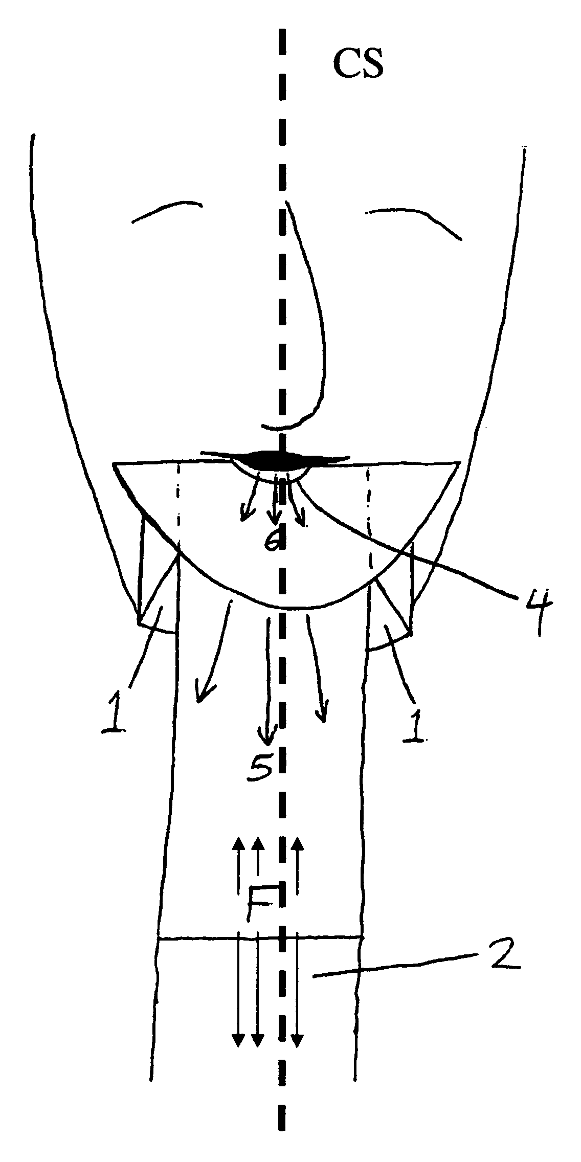
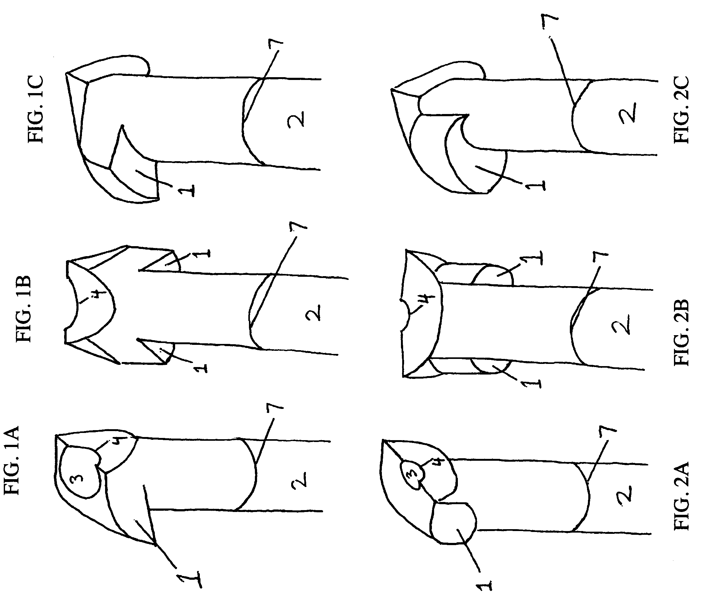
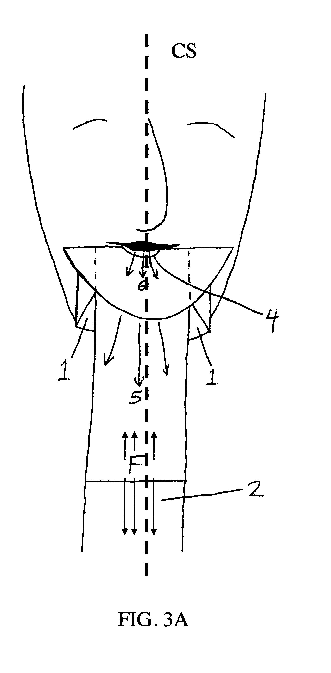
[0023]Embodiments of the present invention are described below with reference to FIG. 1A to FIG. 4B.

[0024]In the drawings, reference numeral 1 denotes the tuning chamber that is formed at the proximal end of a musical instrument, e.g., a flute. The tuning chamber may be a component of the head-joint of the instrument, or may be a component of the instrument itself where the instrument does not comprise a separable head-joint as described herein. Reference numeral 2 denotes the body of the instrument comprising a fluid air space (F), i.e., that air space generally defined by the sound chamber and central bore of the instrument. Reference numeral 3 denotes the embouchure hole, which hole is located, at least in part, through the proximal surface of the tuning chamber, and reference numeral 4 denotes the air reed on the anterior surface of the head-joint and / or instrument, which, in some embodiments, is formed from a portion of the embouchure hole. Reference numeral 7 denotes the point...


PUM


Abstract

The present invention is directed to musical instruments that are based on the operation of an air reed and, in particular, encompasses end-blown flutes comprising an acoustic air space and a fluid air space. The communication between the acoustic and fluid air spaces is positioned so as to minimally interfere with the flow of air introduced, i.e., blown, into the fluid space and enables the instrument to produce rich, in-tune tones across a three octave range. The acoustic air space is formed by a hollow tuning chamber positioned opposite the air reed. In alternate embodiments, the invention encompasses a head-joint of a musical instrument, which head joint comprises a an acoustic space and a fluid space. The head joint of the invention may be used to replace or in place of the head joint or mouthpiece of common musical instruments of the woodwind family, e.g., the Western flute, saxophone, clarinet, oboe, nay, shakuhachi, or recorder.

Description

1. FIELD OF THE INVENTION[0001]The present invention is directed to musical instruments that are based on the operation of an air reed and, in particular, encompasses end-blown flutes having a sound chamber comprised of an acoustic space and a fluid space. The acoustic space is positioned so as to minimally interfere with the flow of air within the fluid space and enables the instrument to produce rich, in-tune tones across a three octave range. In alternate embodiments, the invention encompasses a head-joint of a musical instrument, which head joint comprises a sound chamber having an acoustic space and a fluid space. The head joint of the invention may be used to replace or in place of the head joint or mouthpiece of common musical instruments of the woodwind family, e.g., the Western flute, saxophone, clarinet, oboe, nay, shakuhachi, etc.2. BACKGROUND OF THE INVENTION[0002]The present invention is directed to musical instruments, commonly known as flutes, that are based on the op...

Claims


Application Information

Patent Timeline
Patent Type & Authority Patents(United States)
IPC IPC(8): G10D7/02
CPCG10D7/026
Inventor ROZIER, CLAUDE
Owner ROZIER CLAUDE
Why Eureka
Try Eureka