Systems and methods to shape laser light as a line beam for interaction with a substrate having surface variations

a technology of laser light and surface variation, applied in the field of system and method of shaping laser light as a line beam, can solve the problems of poor grain quality, non-flat surface profile, and unsatisfactory crystal quality of new grains

Active Publication Date: 2010-03-16
CYMER INC
View PDF252 Cites 0 Cited by
  • Summary
  • Abstract
  • Description
  • Claims
  • Application Information

AI Technical Summary

Problems solved by technology

More specifically, failure to obtain a steep sidewall on the trailing short-axis edge may result in the undesirable crystal quality of new grains near the short-axis edge due to insufficient overlap between adjacent pulses.
High energy density levels may cause the film to flow resulting in undesirable “thin spots”, a non-flat surface profile and poor grain quality.
This uneven distribution of film material is often termed “agglomeration” and can render the crystallized film unsuitable for certain applications.
On the other hand, low energy density levels may lead to incomplete melting and result in poor grain quality.
Thus, surface variations of the silicon film, the glass substrate and the vacuum chuck surface which holds the glass substrate, even variations as small as a few microns, if unaccounted for, can lead to unwanted variations in average energy density from one film location to another.
It is to be appreciated that these surface variations can be especially problematic for focused thin beam having a DOF of only about 20 microns.
However, an increase in the numerical aperture of the optical system typically results in a commensurate decrease in the depth of field.

Method used


Image

  • Systems and methods to shape laser light as a line beam for interaction with a substrate having surface variations
  • Systems and methods to shape laser light as a line beam for interaction with a substrate having surface variations
  • Systems and methods to shape laser light as a line beam for interaction with a substrate having surface variations

Examples


Embodiment Construction

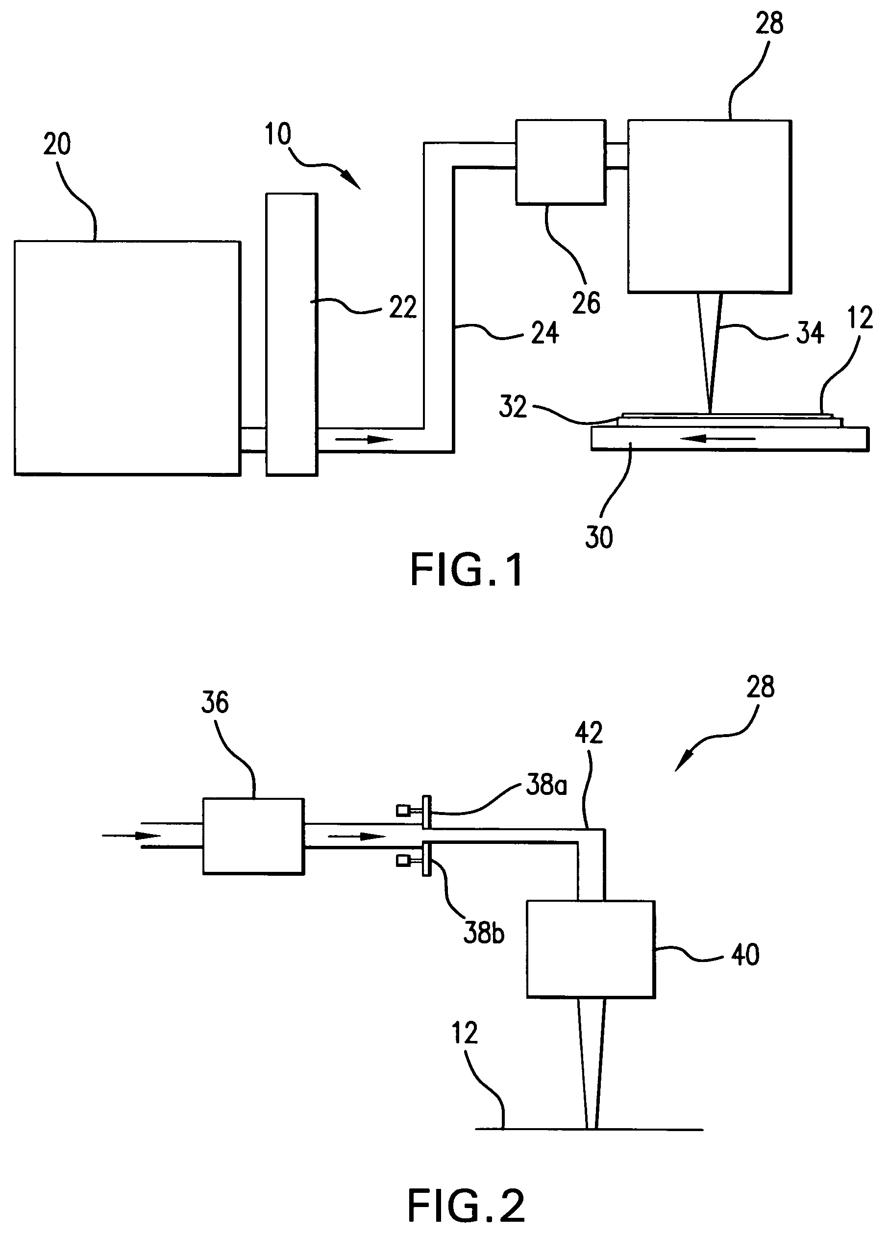
[0022]Referring initially to FIG. 1, there is shown a schematic, not to scale, view of the primary components of a production system, designated generally system 10, for crystallizing an amorphous silicon film 12. As shown, the system 10 may include a laser source 20 for generating a pulsed laser beam, a pulse stretcher 22 for increasing pulse duration and a beam delivery unit 24 which may have a mechanism to actively steer the beam and / or an active beam expander.

[0023]In overview, the laser source 20 may be a two chamber laser having a power oscillator and a power amplifier, and accordingly, is often referred to as a so-called POPA laser source. In one implementation of the crystallization process described above, a 6 Khz (6000 pulses per second) POPA laser may be used with pulse energies of approximately 150 mJ. With this arrangement, a 730 mm×920 mm film may be processed (with 60 percent overlap) in about 75 seconds. The power oscillator and the power amplifier each comprise a di...


PUM

PropertyMeasurementUnit
widthaaaaaaaaaa
thicknessaaaaaaaaaa
lengthaaaaaaaaaa

Abstract

Systems and methods are disclosed for shaping laser light as a line beam for interaction with a film that may have an imperfect, non-planar surface. The system may include a beam stop that defines an edge; a sensor that measures a distance between a selected point on a surface of the film and a reference plane and generates a signal representative of the measured distance; and an actuator coupled to the beam stop and responsive to the signal to move a portion of beam stop edge. Movement of the beam stop edge portion shifts a corresponding portion of the focused line beam in a direction normal to the reference plane to produce a line beam that more closely conforms to the surface profile of the film.

Description

CROSS-REFERENCE TO RELATED APPLICATIONS[0001]The present invention is related to U.S. application Ser. No. 10 / 781,251, titled “VERY HIGH ENERGY, HIGH STABILITY GAS DISCHARGE LASER SURFACE TREATMENT SYSTEM,” filed on Feb. 18, 2004, to U.S. application Ser. No. 10 / 884,101, titled “LASER THIN FILM POLY-SILICON ANNEALING OPTICAL SYSTEM,” filed on Jul. 1, 2004, and to U.S. application Ser. No. 11 / 138,001, titled “SYSTEMS AND METHODS FOR IMPLEMENTING AN INTERACTION BETWEEN A LASER SHAPED AS A LINE BEAM AND A FILM DEPOSITED ON A SUBSTRATE” filed on May 26, 2005, the disclosures of each of which are hereby incorporated by reference herein.FIELD OF THE INVENTION[0002]The present invention relates to systems and methods for shaping laser light as a line beam. Uses of laser light shaped as a line beam may include, but are not necessarily limited to, the melting of an amorphous silicon film to induce crystallization of the film upon resolidification of the melted segment, for the purpose of man...

Claims


Application Information

Patent Timeline
Patent Type & Authority Patents(United States)
IPC IPC(8): B23K26/04B23K26/06B23K26/073
CPCB23K26/0738B23K26/04H01S3/10
Inventor KNOWLES, DAVID S.
Owner CYMER INC
Why Eureka
Try Eureka