Method for lateral motion magnetic resonance imaging

a magnetic resonance imaging and lateral motion technology, applied in the field of magnetic resonance imaging apparatus and procedures, can solve the problems of imposing significant physical constraints on the positioning of patients, unable to achieve the advantages of the patient handling system as discussed in the aforementioned applications, and unable to achieve the advantages of the patient handling system, so as to achieve the effect of faster and more accurate diagnosis of painful injuries and faster image acquisition

Active Publication Date: 2010-03-16
FONAR
View PDF24 Cites 34 Cited by
  • Summary
  • Abstract
  • Description
  • Claims
  • Application Information

AI Technical Summary

Benefits of technology

[0015]The method further desirably includes imaging the patient in a coronal scan or axial scan orientation. Both the axial scan and coronal scan orientations offer advantages over the prior art by allowing for speedy and more accurate diagnosis of painful injuries associated with the spine.
[0016]The method further desirably comprises the step of controlling the movement of the patient. By controlling the patient's movement the images obtained via the scan are more accurate and such images may be obtained more quickly. Such controls may be achieved by placing supports in a plane in front of and / or behind the patient.
[0017]Further in accordance with an aspect of the present invention, the patient may be positioned such that the patient is facing a pole face of the magnetic resonance imaging apparatus. In this way the patient is able to move laterally over an angle large enough to allow for imaging and subsequent diagnosis in a position that causes discomfort or pain to the patient.
[0018]These and other advantages may be realized in an MRI apparatus comprising a pair of pole faces that define a patient receiving space therebetween. The apparatus further desirably includes a patient support capable of supporting a patient in weight bearing position and flux generating means for acquiring images of a patient positioned in the receiving space as the patient moves laterally.

Problems solved by technology

Also, magnetic resonance imaging can obtain images of soft tissues and other features within the body which are not readily visualized using other imaging techniques.
Several factors impose significant physical constraints in positioning of patients and ancillary equipment in MRI imaging.
Moreover, equipment of this type provides a claustrophobic environment for the patient.
Thus, many of the advantages of the patient handling system as discussed in the aforementioned applications are unavailable.

Method used


Image

  • Method for lateral motion magnetic resonance imaging
  • Method for lateral motion magnetic resonance imaging
  • Method for lateral motion magnetic resonance imaging

Examples


Embodiment Construction

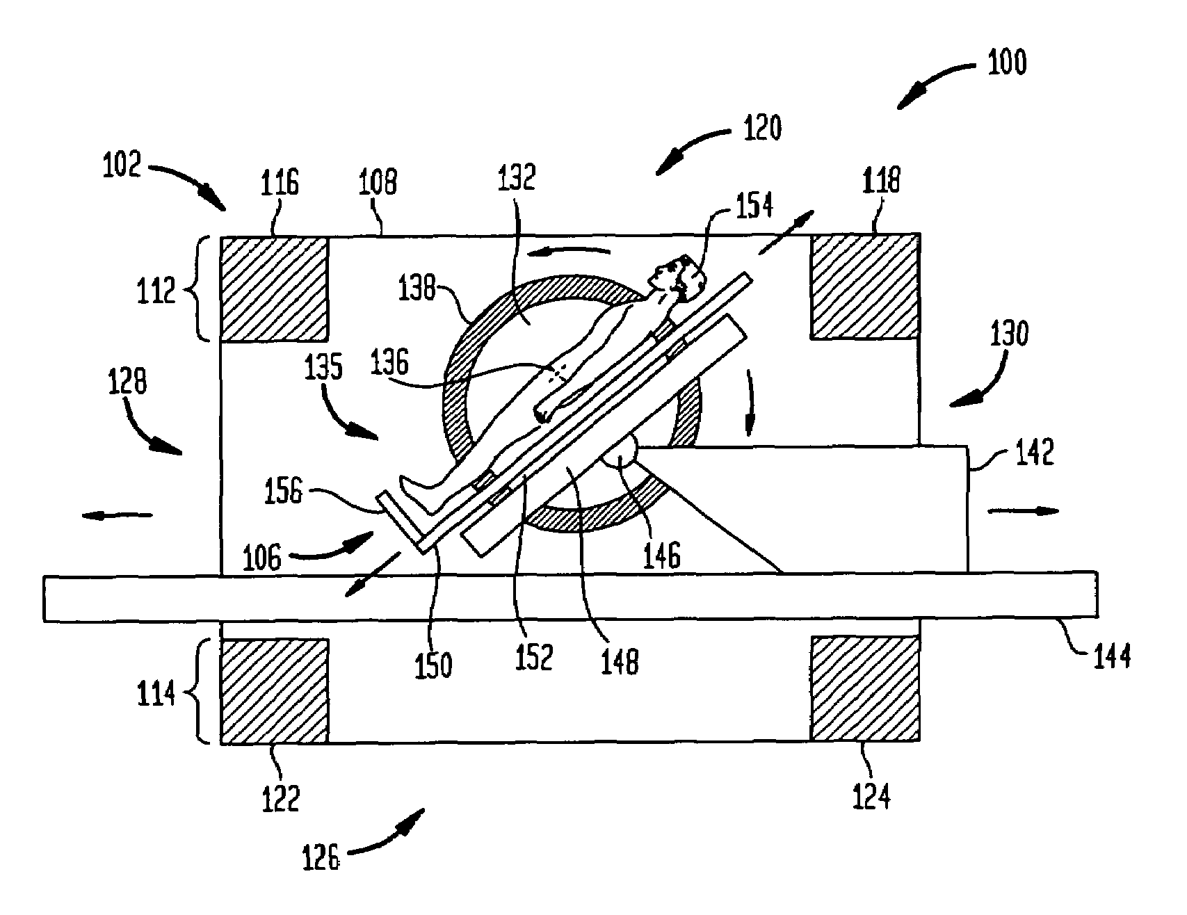
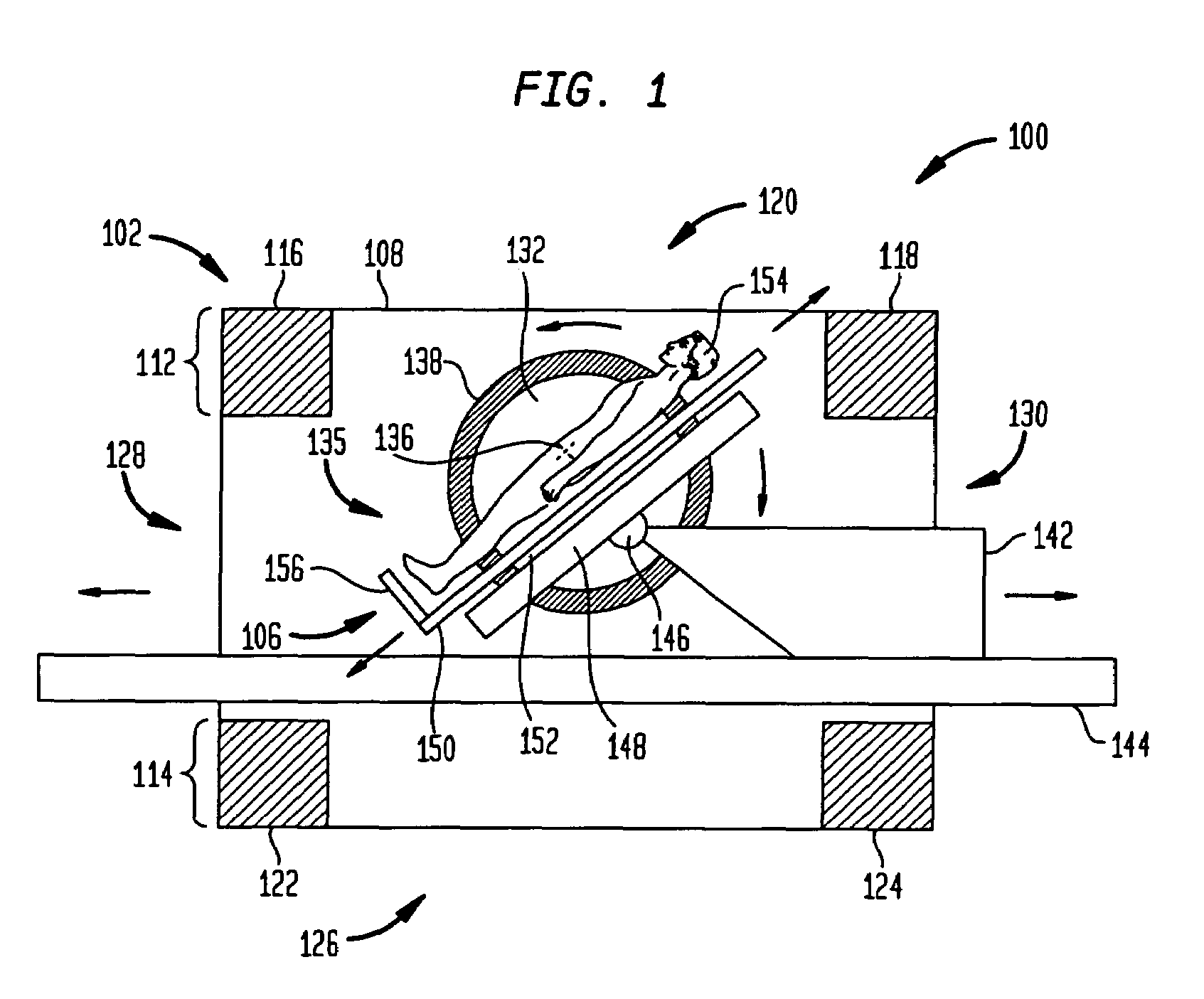
[0029]Among the various positions a patient can assume during a scan are standing while facing out of the magnet, as shown in FIG. 3, as well as standing while rotated 90 degrees from this position, thus facing one of the magnet poles, as shown in FIG. 4. This latter position is particularly advantageous for studies of the spine, including the cervical, lumbar, and thoracic spine.

[0030]FIG. 5 is a sectional view taken along line 9-9 in FIG. 4. To illustrate how this may be used, consider the following study of the lumbar spine. A patient can be positioned standing in the magnet facing one of the poles of the magnet. In this position, the patient may engage in lateral or side-to-side motion generally pivoting about the hip region of the body, as shown in FIG. 5. Images may then be taken at a series of sequential body positions along the path of this lateral motion. Here, a preferred scan orientation is coronal.

[0031]Once this series of scans is complete, they may be diagnosed or anal...


PUM


Abstract

The method includes positioning a patient within a receiving space of a stand-up MRI apparatus and imaging the region of interest of the patient while the patient moves the region of interest. Further in accordance with the method the patient may be positioned such that the patient faces a pole face of a magnet of the MRI apparatus. The apparatus comprises a patient support which allows imaging of a patient's spine with a gravitational load on the spinal system.

Description

CROSS-REFERENCE TO RELATED APPLICATIONS[0001]The present application claims the benefit of U.S. Provisional Application No. 60 / 333,384, filed Nov. 26, 2001 and entitled “METHOD AND APPARATUS FOR MAGNETIC RESONANCE IMAGING,” and U.S. Provisional Application No. 60 / 370,677, filed Apr. 8, 2002 and entitled “METHOD AND APPARATUS FOR MAGNETIC RESONANCE IMAGING,” the disclosures of which are incorporated by reference herein in their entirety.BACKGROUND OF THE INVENTION[0002]The present invention relates to magnetic resonance imaging apparatus and procedures. In magnetic resonance imaging, an object to be imaged as, for example, a body of a human subject is exposed to a strong, substantially constant static magnetic field. Radio frequency excitation energy is applied to the body, and this energy causes the spin vectors of certain atomic nuclei within the body to rotate or “precess” around axes parallel to the direction of the static magnetic field. The precessing atomic nuclei emit weak ra...

Claims


Application Information

Patent Timeline
Patent Type & Authority Patents(United States)
IPC IPC(8): A61B5/05
CPCA61B5/0555A61B5/055
Inventor DAMADIAN, RAYMOND V.SHENOY, RAJENDRADAMADIAN, JEVAN
Owner FONAR
Why Eureka
Try Eureka