Disc brake

a disc brake and disc brake technology, applied in the direction of brake discs, braking systems, transportation and packaging, etc., can solve the problems of uneven heating, achieve the effects of wide gaps, reduce the risk of crack formation, and widen the gap between the material thickness of each tooth

Inactive Publication Date: 2010-03-23
HALDEX BRAKE PROD AB
View PDF14 Cites 8 Cited by
  • Summary
  • Abstract
  • Description
  • Claims
  • Application Information

AI Technical Summary

Benefits of technology

[0011]One option to reduce the risk of crack formation is to have relatively wide gaps between adjacent teeth.
[0012]Another option is to reduce the material thickness in each tooth and / or areas adjacent to the tooth. As an alternative at least some of the areas of reduced material thickness may be replaced by holes in each tooth and / or in an area adjacent to the tooth. The holes may have either an axial or a radial extension. Holes of any direction and other areas of reduced thickness may be combined in many different ways. By these measures the resistance against forced tension in the teeth and the material radially outside the teeth will be reduced and assist in distributing the forced tension more even between the material outside the teeth and the material outside the gaps between the teeth. Material thickness is defined in the direction of the rotational axis of the disc. Furthermore, the material thickness is determined as a net thickness, i.e. hole dimensions are subtracted from the total outer dimensions.
[0013]A further option is to optimise the form of the tooth roots and the bottom of the gap between adjacent teeth. If the radius at the root of a tooth is relatively large and the bottom of the gap has a straight or almost straight part a more even distribution of the tensions is achieved in the brake disc. In practice the bottom of the gap may often have a small bend, e.g. due to manufacturing procedures. By proper design of the radius at the transition, in relation to the size of the straight part of the bottom of the gap, the risk of crack formation is reduced.
[0014]Yet a further option is to form the brake disc with varying properties, to increase the ability to withstand tensions. The material in the area of the teeth may be treated to stand higher tension than the material in the rest of the disc. Brake discs are often made of cast iron as it provides good thermal conductivity. Cast iron, in its most common form with flaked graphite, is a brittle material with poor ability to stand forced tension. By use of particular alloy elements and a well-controlled casting process the cast iron can be modified to get its graphite particles either in the form of spheres, called nodular iron or ductile iron, or in a worm-like form, called compacted graphite iron. In practice the cooling at casting or forging is controlled, which together with the choice of material give the desired effect of different properties of different parts of the brake disc.

Problems solved by technology

A major problem regarding the brake disc is that it will be unevenly heated during braking.

Method used


Image

  • Disc brake
  • Disc brake
  • Disc brake

Examples


Embodiment Construction

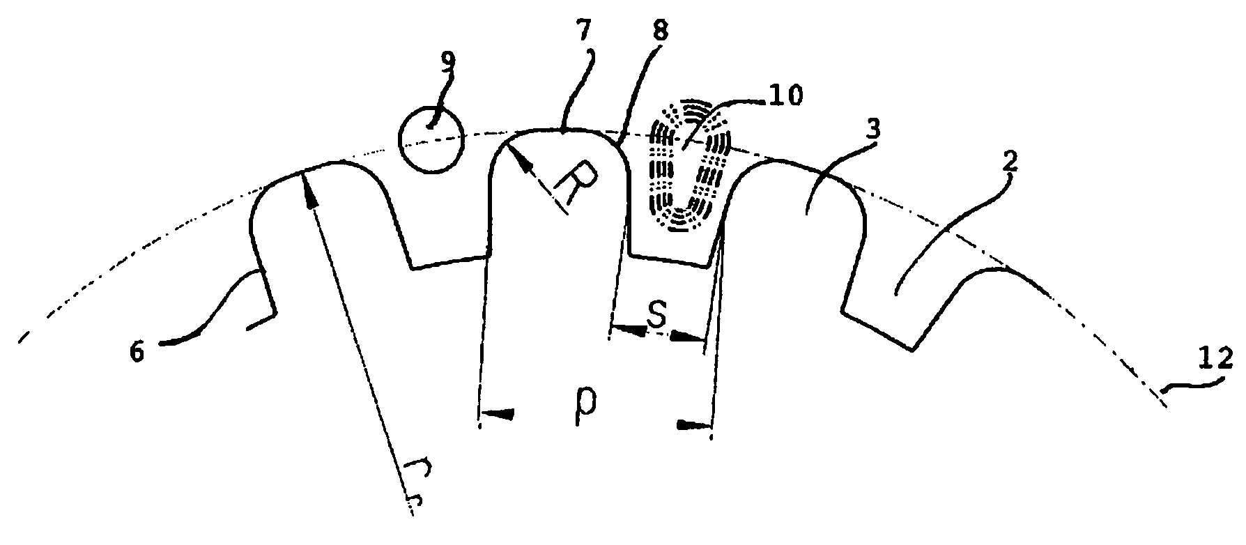
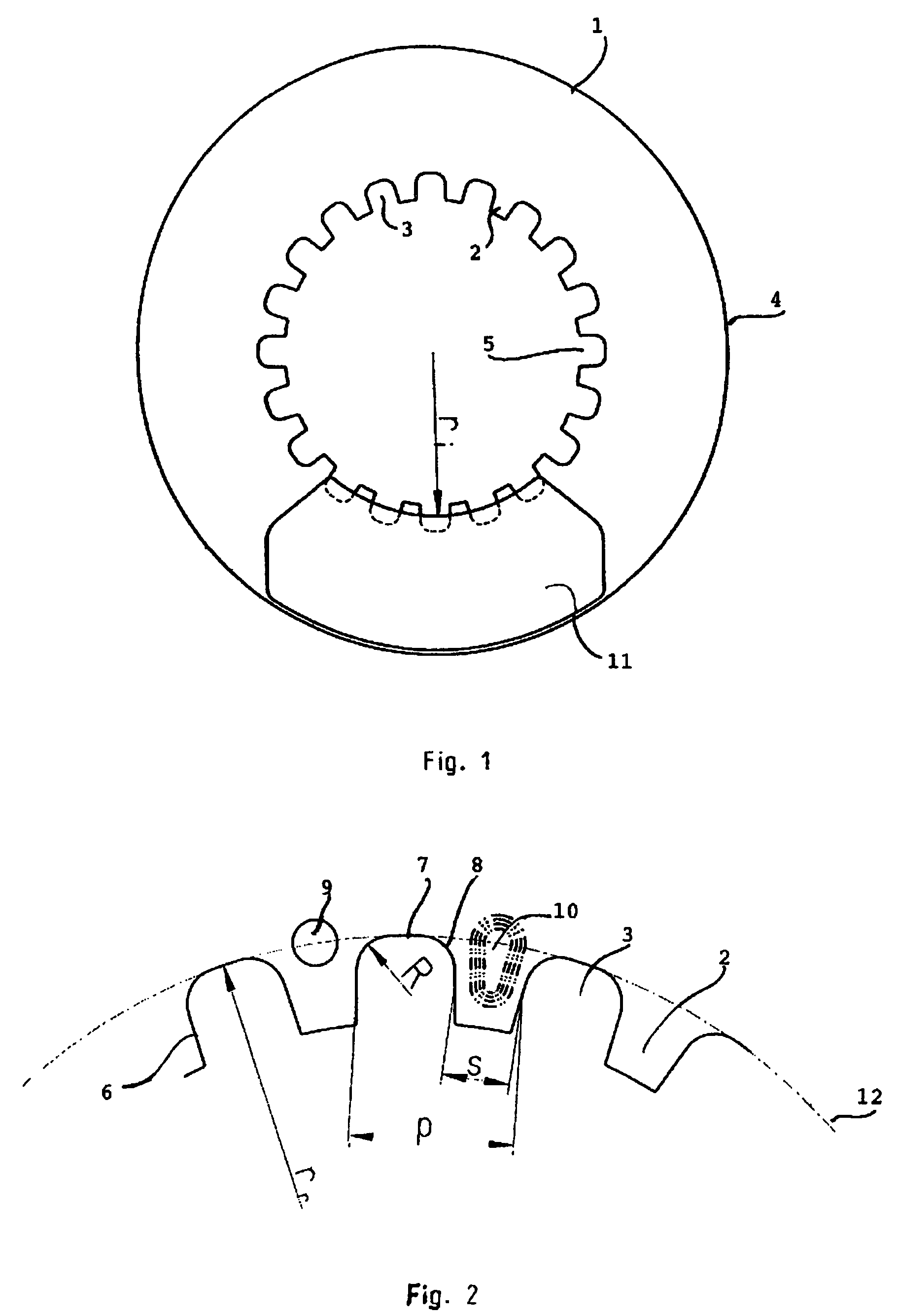
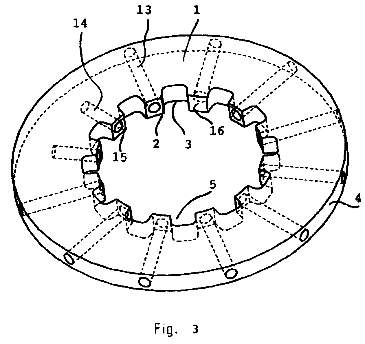
[0020]The brake disc 1 of FIG. 1 has a number of teeth 2 separated by gaps 3. The brake disc 1 is circular with an outer circumference 4 and an inner circumference 5. The teeth 2 are arranged on the inner circumference 5 of the brake disc 1. The brake disc 1 is to be received on a hub or other central part (not shown) of a disc brake. The teeth 2 of the brake disc 1 are to co-operate with teeth, splines or the like on the central part. The disc 1 is received on the central part fixed in rotational direction and is received either fixed or moveable in axial direction. A person skilled in the art realises that the number of teeth 2 and gaps 3 may vary from brake disc 1 to brake disc. Also the form, placement and size of the teeth 2 and gaps 3 may vary both between different discs 1 and in one disc 1. Groups of teeth 2 may e.g. be separated by gaps being larger than the gaps between the teeth of the group in one and the same brake disc.

[0021]Brake pads 11 or the like will coact with th...


PUM


Abstract

A brake disc for a disc brake having one or more sliding or not sliding discs on a hub or other central part is provided. The brake disc has an outer circumference and an inner circumference with a number of alternating teeth and gaps on the inner circumference. One or more measures are taken to reduce the risk of crack formation. One of the measures is to arrange areas of reduced material thickness at and / or adjacent each tooth. The areas of reduced material thickness may be openings having an axial or radial extent. Other measures include designing the teeth and gaps in an appropriate way and forming the brake disc with different properties at different parts.

Description

CROSS-REFERENCE TO RELATED APPLICATIONS[0001]The present application is a continuation of pending International patent application PCT / SE2004 / 001795 filed on Dec. 3, 2004 which designates the United States and claims priority from Swedish patent application 0303279-4 filed on Dec. 5, 2003, the content of which is incorporated herein by reference.FIELD OF THE INVENTION[0002]The present invention concerns a brake disc to be used in a disc brake having one or more sliding or not sliding discs on a hub, a central part connected to the hub or any similar part. The present invention concerns the type of brake discs having teeth or the like on an inner circumference.BACKGROUND OF THE INVENTION[0003]For disc brakes having one or more sliding discs the discs are normally received on a hub or other central part rotating in conjunction with the associated wheel. To simplify the description the term “central part” is used in a broad sense and is to be construed as covering any part receiving th...

Claims


Application Information

Patent Timeline
Patent Type & Authority Patents(United States)
IPC IPC(8): F16D65/12
CPCF16D65/12F16D2065/1328F16D2065/1368F16D2200/0013F16D2250/0007
Inventor GRIPEMARK, JOAKIMKALL, PATRIKSTENSSON, GORAN
Owner HALDEX BRAKE PROD AB
Why Eureka
Try Eureka