Asphalt tamper

Inactive Publication Date: 2010-03-23
BURKE GARY +1
View PDF18 Cites 42 Cited by
  • Summary
  • Abstract
  • Description
  • Claims
  • Application Information

AI Technical Summary

Benefits of technology

[0017]A further object of the invention is to provide a variable spee

Problems solved by technology

As will be discussed immediately below, no prior art discloses a lightweight motorized tamper that includes a variable speed control and an electric motor that is powered via a rechargeable battery.
However, the vibrating tamper of Grane is big and bulky and not as lightweight as the asphalt tamper claimed below.
However, the tamper is a part of a patching

Method used


Image

  • Asphalt tamper
  • Asphalt tamper
  • Asphalt tamper

Examples


Example

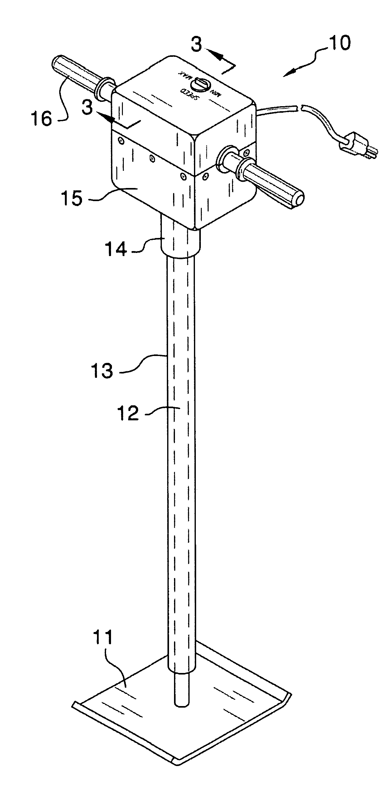
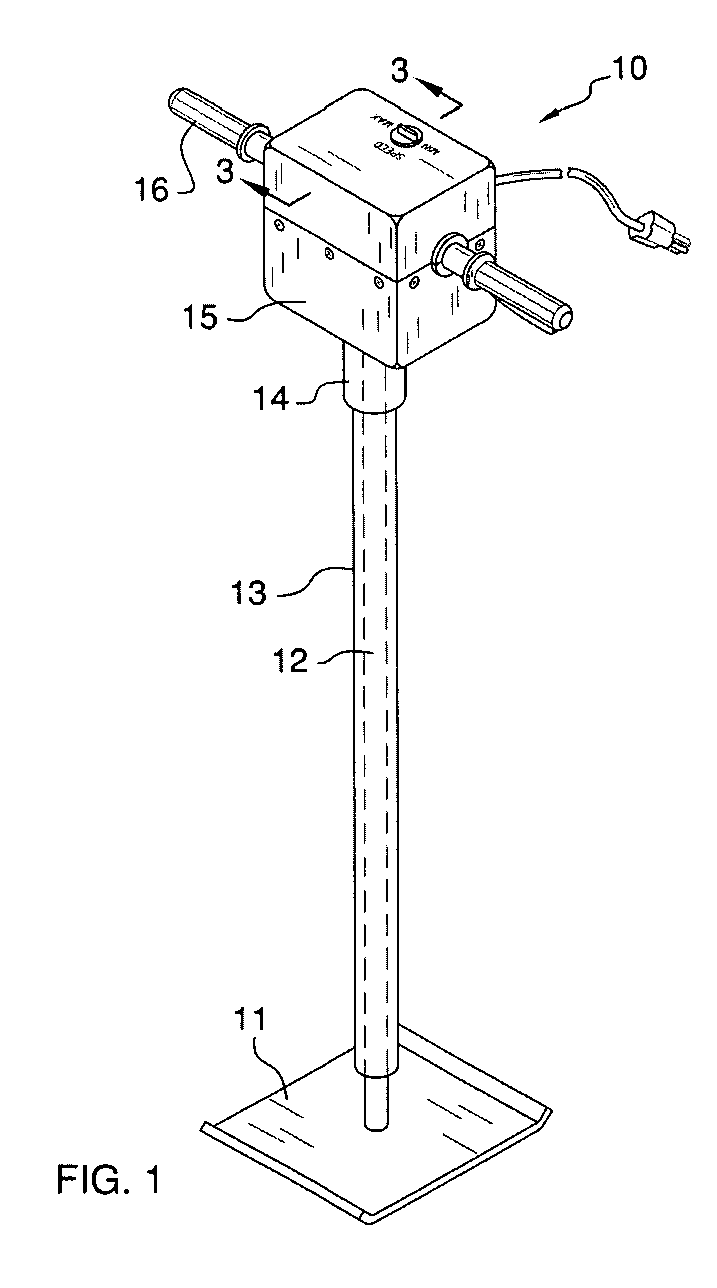
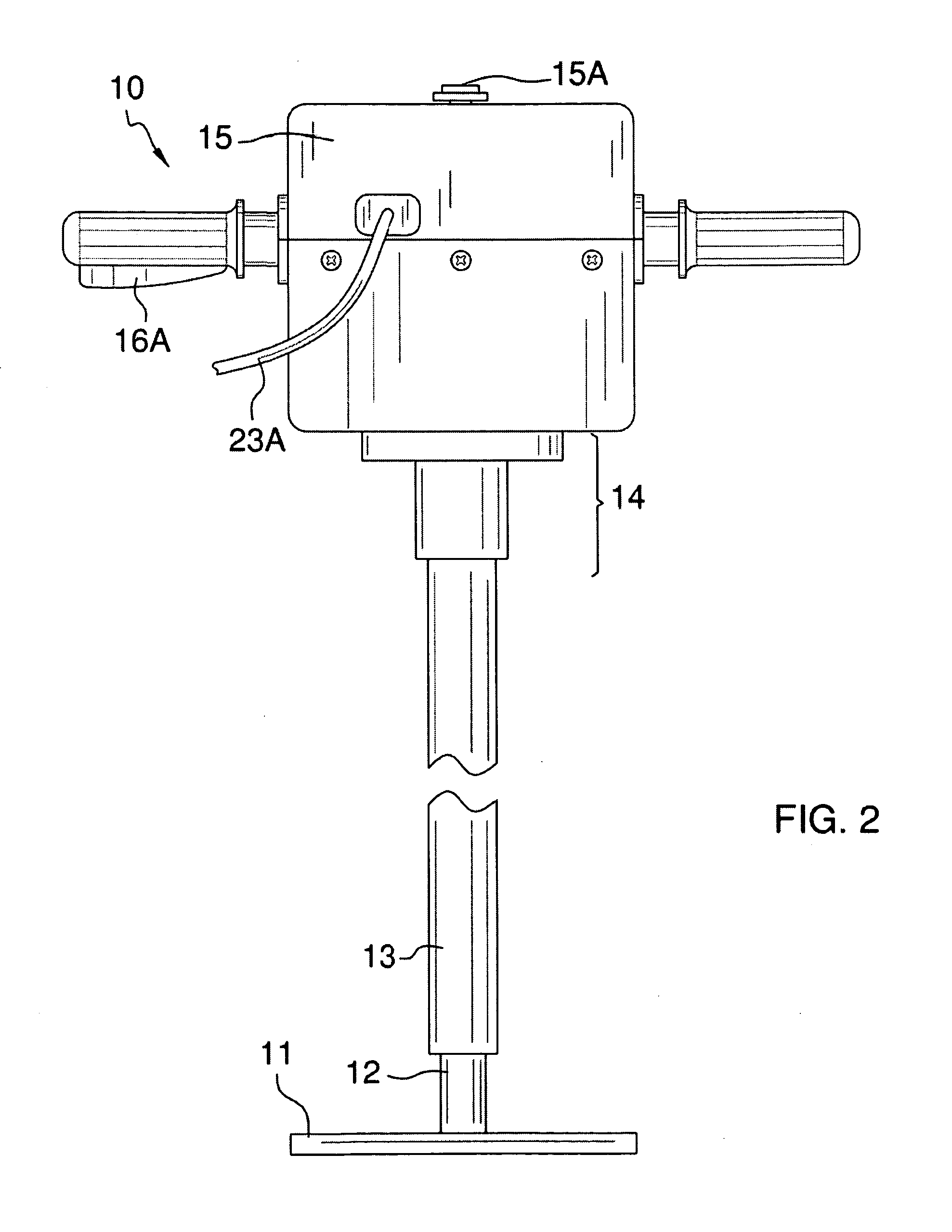
[0027]Detailed reference will now be made to the preferred embodiment of the invention, examples of which are illustrated in FIGS. 1-3. A tamping device 10 (hereinafter invention) comprises a tamping plate 11, reciprocating rod 12, sleeve 13, sub-housing 14, housing 15, and handles 16.

[0028]The sleeve 13 runs along the reciprocating rod 12 and protects the reciprocating rod 12. The sleeve 13 is made of a material comprising a metal, rubber, plastic, or carbon fiber composite. The reciprocating plate 12 shall be no less than 3 feet in overall length. The reciprocating rod 12 shall have the ability to move back and forth within both the sub-housing 14 and the housing 15 via openings 14A / 15B, respectively. A plurality of bushings 148 are included within the sub-housing 14 to enable a means of sealing off the openings 14A / 15B from outside debris while reducing friction between the reciprocating rod and the sub-housing 14.

[0029]The reciprocating plate 12 and the tamping plate 11 are made...


PUM


Abstract

The asphalt tamper includes a tamper plate connected to a reciprocating rod that oscillates inside of a protective sleeve, wherein the reciprocating rod abuts a cam that rotates about the output of a motor. The reciprocating rod has a shoulder that interacts with a spring that applies a biasing force ushering the reciprocating rod back and forth upon interaction with the rotating cam.

Description

CROSS REFERENCES TO RELATED APPLICATIONS[0001]Not ApplicableSTATEMENT REGARDING FEDERALLY SPONSORED RESEARCH[0002]Not ApplicableREFERENCE TO APPENDIX[0003]Not ApplicableBACKGROUND OF THE INVENTION[0004]A. Field of the Invention[0005]The present invention relates to the field of motorized tampers, more specifically, a hand-held tamper that has a variable speed control and is powered by an electric motor.[0006]Manual or motorized tampers have been around for a long time, and provide a valuable service in compacting various types of ground. However, traditional motorized tampers are bulky and do not have variable speed control, or the option to be electrically powered. A variable speed control for a motorized tamper expands the range of different surfaces that require different tamping speeds. The present invention seeks to improve this field of prior art and overcome these limitation by providing a motorized tamper that is lightweight when compared to the prior art, has a variable spe...

Claims


Application Information

Patent Timeline
IPC IPC(8): E01C19/35E01C19/34
CPCE01C19/35
Inventor BURKE, GARYBURKE, DALE
Owner BURKE GARY
Why Eureka
Try Eureka