

Calculus manipulation apparatus
a technology of manipulating apparatus and calculus, which is applied in the field of manipulating apparatus, can solve problems such as the inability to ensure a satisfactory crushing for
- Summary
- Abstract
- Description
- Claims
- Application Information
AI Technical Summary
Benefits of technology
Problems solved by technology
Method used
Image

Examples
first embodiment
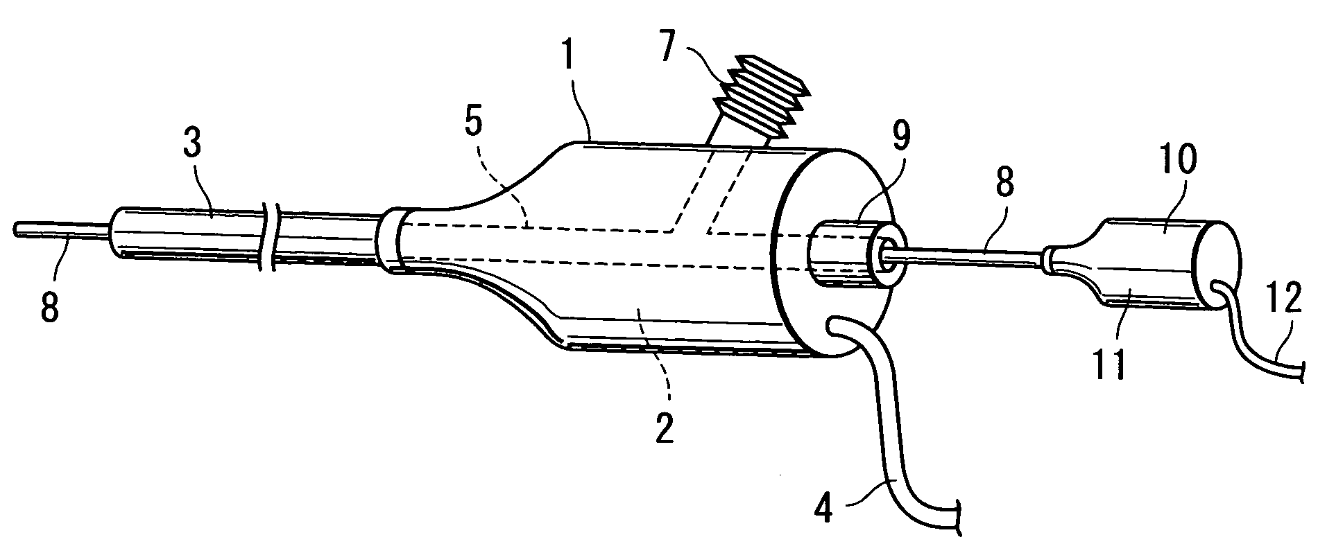
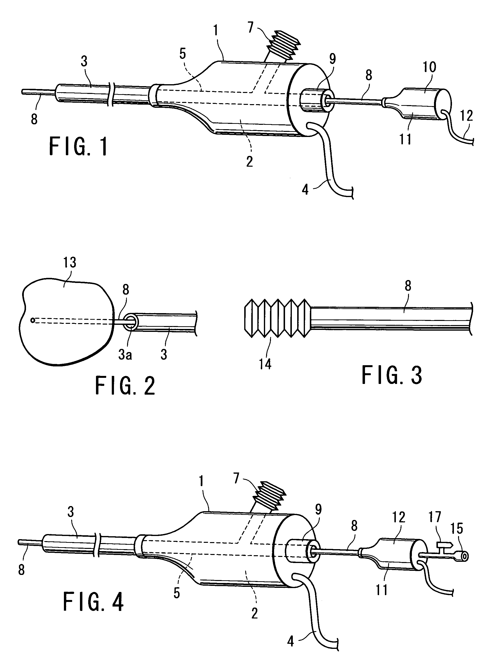
[0070]An ultrasonic lithotripter according to the present invention will now be described with reference to FIGS. 1 and 2. The ultrasonic lithotripter of the present embodiment comprises a grip section 1. The grip section 1 has therein an ultrasonic generator element 2 for lithotripsy that is composed of a vibrator. The proximal end portion of a hollow first transmission probe 3 is connected mechanically to the ultrasonic generator element 2 by means of a horn (not shown). An ultrasonic manipulator element 3b is provided on the distal end of the first transmission probe 3.
[0071]A power supply unit (not shown) is connected to the ultrasonic generator element 2 by means of a power cord 4. In starting operation, electrical energy is supplied from the power supply unit to the ultrasonic generator element 2 for lithotripsy. The ultrasonic generator element 2 converts the electrical energy into ultrasonic vibration. This ultrasonic vibration is transmitted through the hollow transmission ...
second embodiment
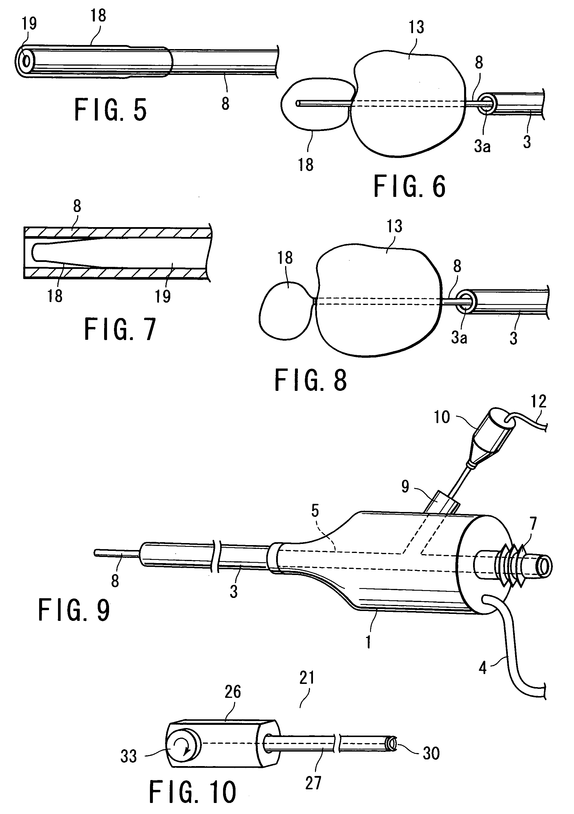
[0089]The superfine transmission probe 8 of the present embodiment, like that of the second embodiment, is in the form of a hollow pipe. As shown in FIG. 7, an inflatable elastic balloon 18 is located in the distal end portion of a hollow portion 19 of the probe 8. Normally, the balloon 18 is deflated as it is drawn into the hollow portion 19 to be stored therein, as shown in FIG. 7. The balloon 18 is inflated with air that is fed through the hollow portion 19. Thus, the balloon 18 can inflate after it gets out of the distal end of the probe 8, as shown in FIG. 8.
[0090]In operating this ultrasonic lithotripter, the superfine transmission probe 8 is subjected to ultrasonic vibration as the calculus 13 is pierced with it. When this is done, the probe 8 is inserted so that its distal end portion having the balloon 18 therein penetrates the calculus 13. Thereafter, a syringe is used to feed air through a syringe mounting hole 15 of a superfine ultrasonic generator element 10.
[0091]As ai...
fifth embodiment
[0097]FIGS. 10 to 13 show the invention. A calculus catcher 21 is used as a calculus collector that can discharge a staple through its sheath. The calculus catcher 21 is used in combination with a ureteroscope 20 (shown in FIG. 11).
[0098]As shown in FIG. 10, the calculus catcher 21 comprises a control section 26 for use as control mechanism means on the proximal side of the sheath and an insert section 27 in the form of a flexible sheath. The insert section 27 can be passed through a channel of the ureteroscope 20.
[0099]As shown in FIG. 12, a staple anchoring portion 28 is provided at a position corresponding to the extreme end of the insert section 27 of the calculus catcher 21. A staple clamper 29 is located just behind the anchoring portion 28. A staple 30 is removably attached to the anchoring portion 28.
[0100]As shown in FIG. 13, the staple 30 is formed of a C-shaped wire. The opposite end portions of this wire individually form claws 30a that bite the calculus 13. Normally, th...
PUM
 Abstract
Description
Claims
Application Information