Multiple location electronic timer system

a technology of electronic timer and multi-location, applied in the direction of electrical equipment, light sources, electric light circuit arrangements, etc., can solve the problem that the remote electronic timer provides only limited functionality

Active Publication Date: 2010-03-23
LUTRON TECH CO LLC
View PDF73 Cites 42 Cited by
  • Summary
  • Abstract
  • Description
  • Claims
  • Application Information

AI Technical Summary

Benefits of technology

[0007]According to the present invention, a multiple location electronic timer system for controlling the power delivered to an electrical load from an AC power source comprises a wall-mountable electronic timer and a wall-mountable accessory timer. The electronic timer is adapted to be coupled in series electrical connection between the source and the load, and comprises an internal timer, a timer adjustment actuator, and a plurality of visual indicators. The electronic timer is operable to select a preset timeout period in response to an actuation of the timer adjustment actuator, cause the visual indicators to display a representation of the preset timeout period, enable the delivery of power to the load in response to a control signal received directly from the accessory timer, and start the internal timer in response to the control signal received from the accessory timer. The internal timer is initialized with the preset timeout period. The electronic timer is further operable to prevent the delivery of power to the load when the preset timeout period has elapsed.
[0010]According to yet another embodiment of the present invention, a multiple location electronic timer system comprises an electronic timer and a wall-mountable accessory timer comprising a control actuator, a timer adjustment actuator, and a plurality of visual indicators. The electronic timer is adapted to be coupled in series electrical connection between an AC power source and an electrical load, the electronic timer comprising an internal timer. The electronic timer is operable to select a preset timeout period in response to an actuation of the timer adjustment actuator, cause the visual indicators to display a representation of the preset timeout period, enable the delivery of power to the load in response to an actuation of the control actuator, and start the internal timer in response to the actuation of the control actuator. The internal timer is initialized with the preset timeout period. The electronic timer is further operable to prevent the delivery of power to the load when the preset timeout period has elapsed.

Problems solved by technology

However, such remote electronic timers provide only limited functionality (i.e., a user is only able to turn on and off the connected lighting load from the remote control) and no feedback of the operation of the electronic timer.

Method used


Image

  • Multiple location electronic timer system
  • Multiple location electronic timer system
  • Multiple location electronic timer system

Examples


first embodiment

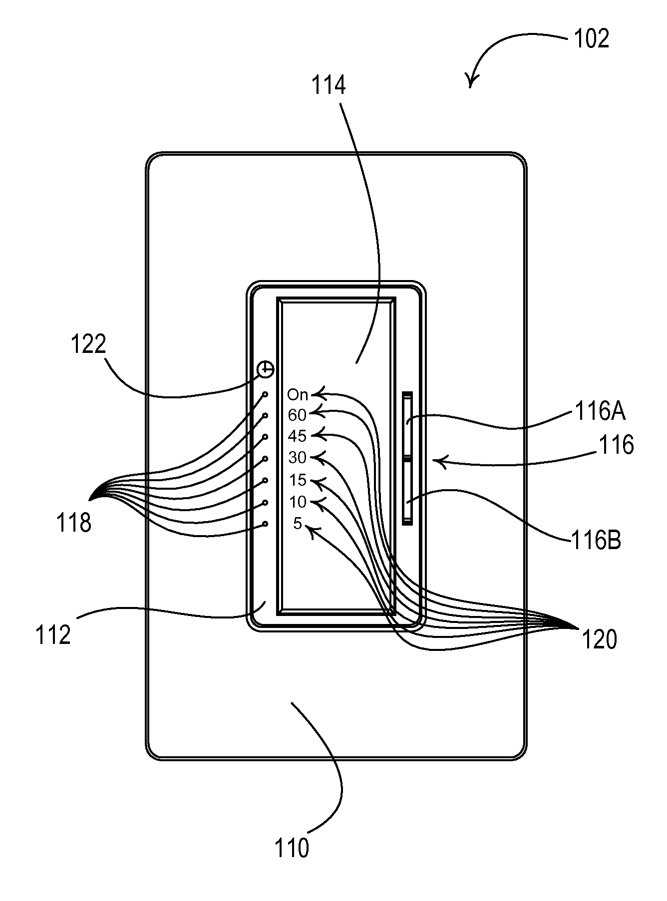
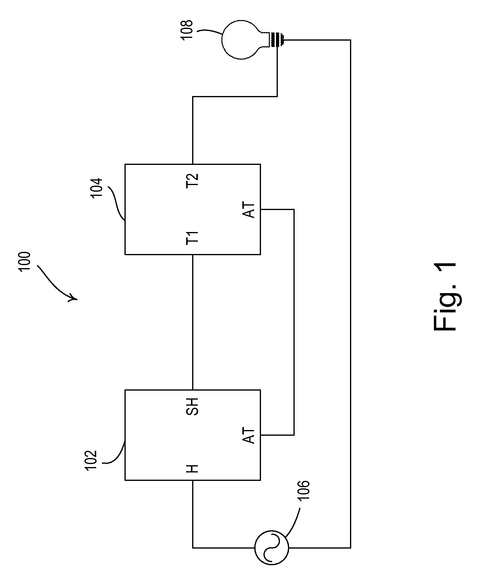
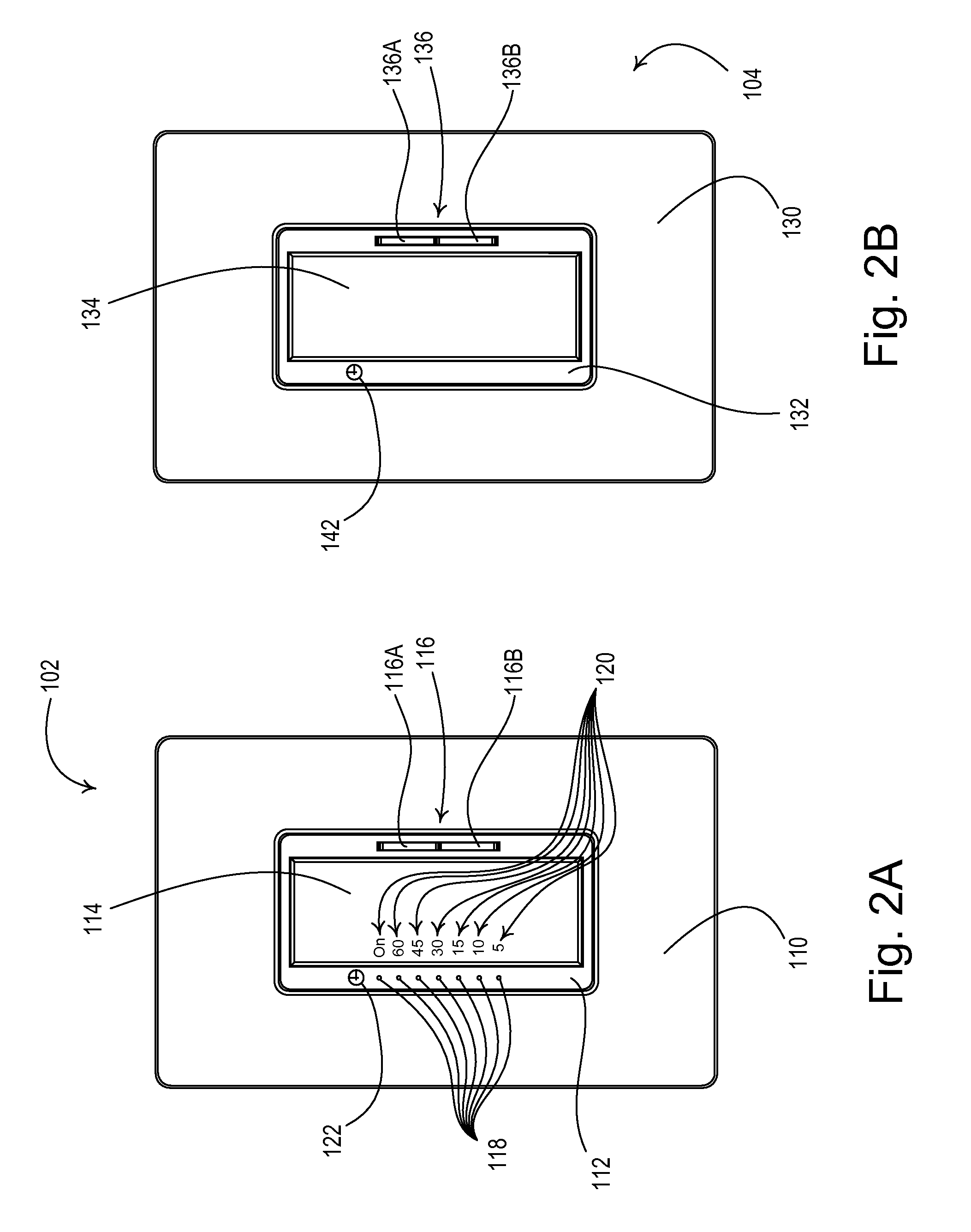
[0032]FIG. 1 is a simplified block diagram of a multiple location electronic timer system 100 according to the present invention. The timer system 100 comprises an electronic timer 102 and an accessory timer 104 (i.e., a plurality of timer control devices). The electronic timer 102 and the accessory timer 104 are both coupled in series between an alternating-current (AC) power source 106 and a connected electrical load, for example, a lighting load 108 or a motor load, such as an exhaust fan. The electronic timer 102 is coupled to the AC power source 106 via a hot terminal H and is coupled to the accessory timer 104 via a switched-hot terminal SH. The accessory timer 104 is coupled to the electronic timer 102 via a first terminal T1 and to the lighting load 108 via a second terminal T2, such that the accessory timer 104 is connected on the load side of the timer system 100 as shown in FIG. 1. Note that the accessory timer 104 could alternatively be coupled to the AC power source 106...

second embodiment

[0066]FIG. 7 is a simplified block diagram of a multiple location electronic timer system 700 according to the present invention. The timer system 700 includes a plurality of accessory timers 104 (e.g., three accessory timers as shown in FIG. 7). The accessory timer terminal AT of each of the accessory timers 104 is coupled to the accessory timer terminal AT of the electronic timer 102, such that the electronic timer 102 is operable to control the lighting load 108 in response to actuations of the control actuator 134 or the timer adjustment actuator 136 of any of the accessory timers 104. Since the accessory timers 104 are essentially coupled in parallel, the electronic timer 102 is responsive to actuations of the control actuators 134 and the timer adjustment actuators 136 of each of the accessory timers.

[0067]The operation of a multiple-location lighting control system that does not include electronic timers is described in greater detail in commonly-assigned U.S. Pat. No. 5,798,...

third embodiment

[0068]FIG. 8 is a simplified block diagram of a radio-frequency (RF) multiple location electronic timer system 800 according to the present invention. The timer system 100 comprises an RF electronic timer 802 coupled between the AC power source 102 and the lighting load 108 and a plurality of RF accessory timers 804 (e.g., two accessory timers as shown in FIG. 8). The electronic timers 802 and the accessory timers 804 all include control actuators 114, 134, timer adjustment actuators 116, 136, and visual indicators 118, 138. The RF timer system 800 uses a two-way RF communication link for communication of RF signals 805 between the electronic timer 802 and the accessory timers 804. Examples of RF lighting control systems are described in greater detail in commonly-assigned U.S. Pat. No. 5,905,442, issued May 18, 1999, entitled METHOD AND APPARATUS FOR CONTROLLING AND DETERMINING THE STATUS OF ELECTRICAL DEVICES FROM REMOTE LOCATIONS, and commonly-assigned U.S. Pat. No. 6,803,728, is...


PUM


Abstract

A multiple location electronic timer system comprises an electronic timer and one or more accessory timers. The electronic timer is adapted to be coupled between an AC power source and an electrical load. The electronic timer is operable to enable the delivery of power to the load and to subsequently discontinue the delivery of power to the load automatically after a preset timeout period has elapsed. In response to controls signals received from the accessory timer, the electronic timer is operable to adjust the preset timeout period, enable the delivery of power to the load, discontinue the delivery of power to the load, and to enter a bypass mode in which the load is turned on for an indefinite amount of time. The accessory timer may be coupled to the electronic timer via a single conductor, a wired digital communication link, a radio frequency communication link, an infrared communication link, or a power line carrier communication link.

Description

RELATED APPLICATIONS[0001]This application is a continuation-in-part of co-pending commonly-assigned U.S. patent application Ser. No. 11 / 521,234, filed Sep. 13, 2006, entitled WALL-MOUNTABLE TIMER FOR AN ELECTRICAL LOAD. This application also claims priority from commonly-assigned U.S. Provisional Patent Application Ser. No. 60 / 860,759, filed Nov. 22, 2006, entitled MULTIPLE LOCATION ELECTRONIC TIMER SYSTEM. The entire disclosures of both applications are hereby incorporated by reference.BACKGROUND OF THE INVENTION[0002]1. Field of the Invention[0003]The present invention relates to load control devices for controlling the amount of power delivered to an electrical load from a source of alternating-current (AC) power, and more particularly, to a multi-location electronic timer system for supplying power to a connected electrical load for a predetermined amount of time selectable by a user.[0004]2. Description of the Related Art[0005]In response to increasing awareness of energy cons...

Claims


Application Information

Patent Timeline
Patent Type & Authority Patents(United States)
IPC IPC(8): H01H7/00
CPCH05B37/0272H05B37/0281Y02B20/42H05B47/16H05B47/19H05B47/195Y02B20/40
Inventor BLAIR, EDWARD J.DOBBINS, AARONVIGUE, NICOLE R.MCCARTER, KYLE A.NEWMAN, JR., ROBERT C.JACOBY, ELLIOT G.
Owner LUTRON TECH CO LLC
Why Eureka
Try Eureka