Handler comprising an acceleration device for testing electronic components

a technology of acceleration device and electronic component, which is applied in the direction of electronic circuit testing, structural/machine measurement, mechanical vibration separation, etc., can solve the problems of affecting the performance of the handler, the linear guidance of the tappet is exposed to extreme loads, and the standard bearings are usually not able to withstand such loads, so as to achieve uniform transmission of power from the tappet, simple and economical production, and uniform application of force

Inactive Publication Date: 2010-03-23
MULTITEST ELEKTRONISCHE SYST
View PDF9 Cites 11 Cited by
  • Summary
  • Abstract
  • Description
  • Claims
  • Application Information

AI Technical Summary

Benefits of technology

[0015]Preferably, the spring arms are arranged evenly distributed in the circumferential direction of the flat spring. As a result, uniform application of force onto the flat spring and uniform transmission of power from the tappet to the frame are ensured.
[0016]The spring arms can be formed in a straight-line or curved, preferably having an S-shaped curved section in the latter case. While straight-line formation of the spring arms permits very simple and economical production of the flat spring, curved spring arms have the advantage that particularly large deflections are possible within a small space, since the length of the spring arms is increased as a result of the curvature.

Problems solved by technology

Here, there is a problem that, due to the movement generation device, for example a coil, secondary accelerations in unintended spatial directions and also rotary movements can be transmitted to the tappet and thus to the component being tested, as a result of which the measurement results can be distorted.
A further problem is that the bearings for linear guidance of the tappet are exposed to extreme loads by the sometimes very high movement frequencies and by temperature ranges of between −55° C. to +155° C., at which these tests are performed.
Standard bearings usually do not withstand such loads and do not have the desired durability.

Method used


Image

  • Handler comprising an acceleration device for testing electronic components
  • Handler comprising an acceleration device for testing electronic components
  • Handler comprising an acceleration device for testing electronic components

Examples


Embodiment Construction

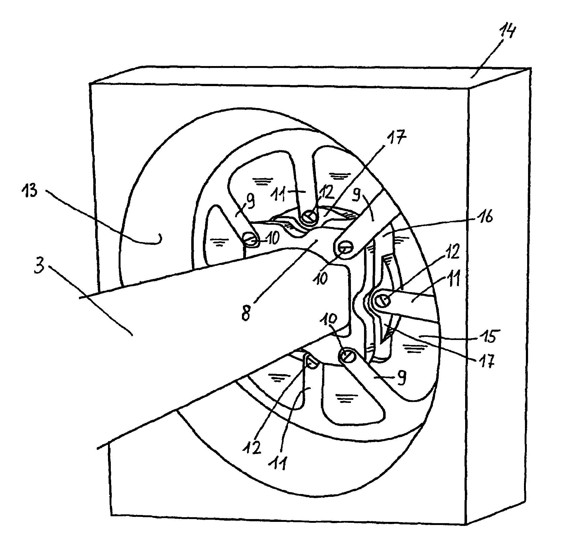
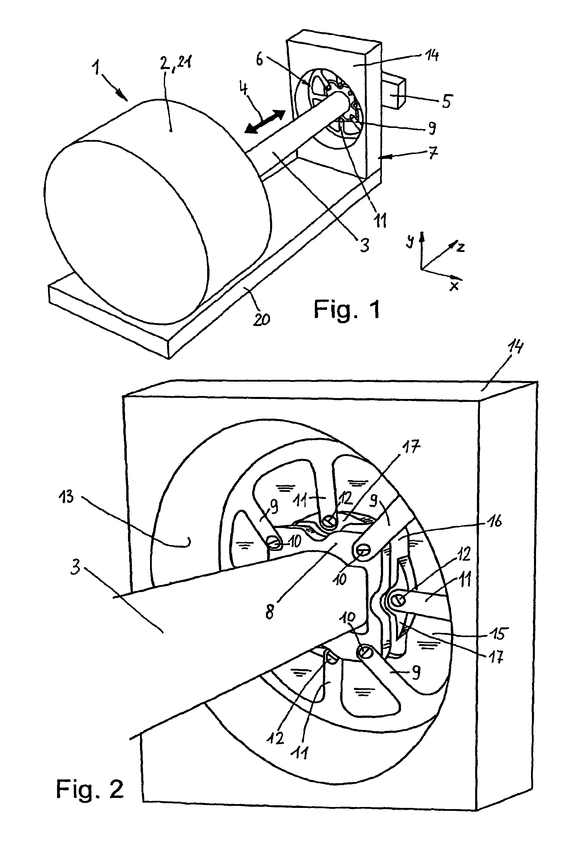
[0027]FIG. 1 shows an acceleration device 1, which is intended to be installed in a handler for electronic components, in order to subject electronic components such as ICs, not illustrated in detail, to an acceleration test.

[0028]For this purpose the acceleration device 1 comprises a movement generation device 2, for example a coil, by means of which a tappet 3 can be moved to and fro in the axial direction, that is to say towards the arrow 4, at a certain frequency. The test frequency here depends on the type of component and the desired target application and can amount to a few hertz or several kilohertz. The tappet 3 in the illustrated exemplary embodiment is a straight rod which, for example, has a round cross section but can also have different cross-sectional shapes.

[0029]A nest 5, that is to say, a receiving device, in which the component being tested is held, can be fixed to the free end of the tappet 3. When the tappet 3 is moved to and fro towards the arrow, the nest 5 a...


PUM


Abstract

The technology herein relates to a handler for testing electronic components, said handler comprising an acceleration device provided with a tappet which is linearly guided by means of at least one flat spring comprising two groups of spring arms, one group being fixed to the tappet and the other group to a frame which is stationary in relation to a housing of the movement generation device. Handler comprising an acceleration device for testing electronic components.

Description

CROSS-REFERENCES TO RELATED APPLICATIONS[0001]This application is the U.S. national phase of International Application No. PCT / EP2007 / 004644, filed 24 May 2007, which designated the U.S. and claims priority to German Patent Application No. 10 2006 025 341.8, filed 31 May 2006, the entire contents of each of which are hereby incorporated by reference.STATEMENT REGARDING FEDERALLY SPONSORED RESEARCH OR DEVELOPMENT[0002]N / AFIELD[0003]The technology herein relates to a handler for testing electronic components comprising a nest to receive the components and an acceleration device, by which the components held in the nest are subjected to acceleration tests, wherein the acceleration device has a tappet, to which the nest can be fixed, as well as a movement generation device for accelerating the tappet in the axial direction.BACKGROUND AND SUMMARY[0004]As is known, handlers serve to feed electronic components, such as ICs for example, to a test head of a test device, so as to contact the ...

Claims


Application Information

Patent Timeline
Patent Type & Authority Patents(United States)
IPC IPC(8): G01R31/28
CPCG01M7/04G01R31/2893G01R31/2881G01R31/26H01L22/00
Inventor KIERMEIER, ARNFRIEDKLIER, MICHAELMUHLBAUER, JOSEF
Owner MULTITEST ELEKTRONISCHE SYST
Why Eureka
Try Eureka