Pneumatic paintball gun

a paintball gun and pneumatic technology, applied in the direction of compressed gas guns, white arms/cold weapons, butts, etc., can solve the problems of complex manufacturing processes, increased manufacturing costs, and complicated manufacturing processes, and achieves simplified loading and firing mechanisms, effective firing, and easy and quick loading and firing mechanisms

Inactive Publication Date: 2010-03-30
GAN YIAUGUO
View PDF4 Cites 7 Cited by
  • Summary
  • Abstract
  • Description
  • Claims
  • Application Information

AI Technical Summary

Benefits of technology

[0010]The primary objective of the present invention is to provide a pneumatic paintball gun including a simplified loading and firing mechanism for allowing the paintball or bullet to be easily and quickly loaded into the firing chamber and to be effectively fired by pressurized air or gas.

Problems solved by technology

However, the loading assembly and the firing assembly are separated from each other and include a relatively complicated structure having a number of parts or elements required to be manufactured and assembled such that the manufacturing processes are complicated and the manufacturing costs will be greatly increased.
However, similarly, the firing device and the gas entry valve are separated from each other and the gun body is required to be formed with two chambers or passages therein for receiving the firing device and the gas entry valve respectively, such that the typical lacquer bullet gun also include a relatively complicated structure having a number of parts or elements required to be manufactured and assembled such that the manufacturing processes are complicated and the manufacturing costs will be greatly increased.

Method used


Image

  • Pneumatic paintball gun
  • Pneumatic paintball gun
  • Pneumatic paintball gun

Examples


Embodiment Construction

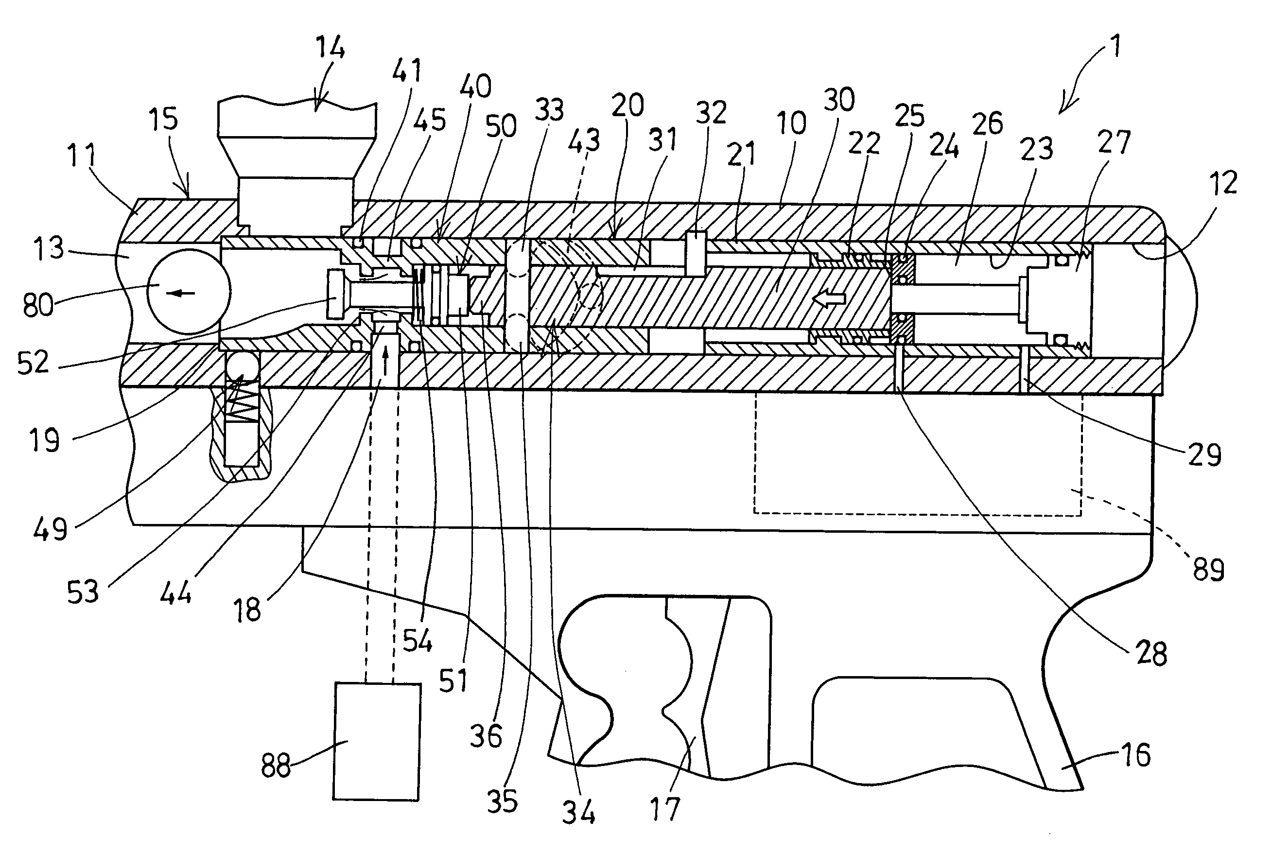
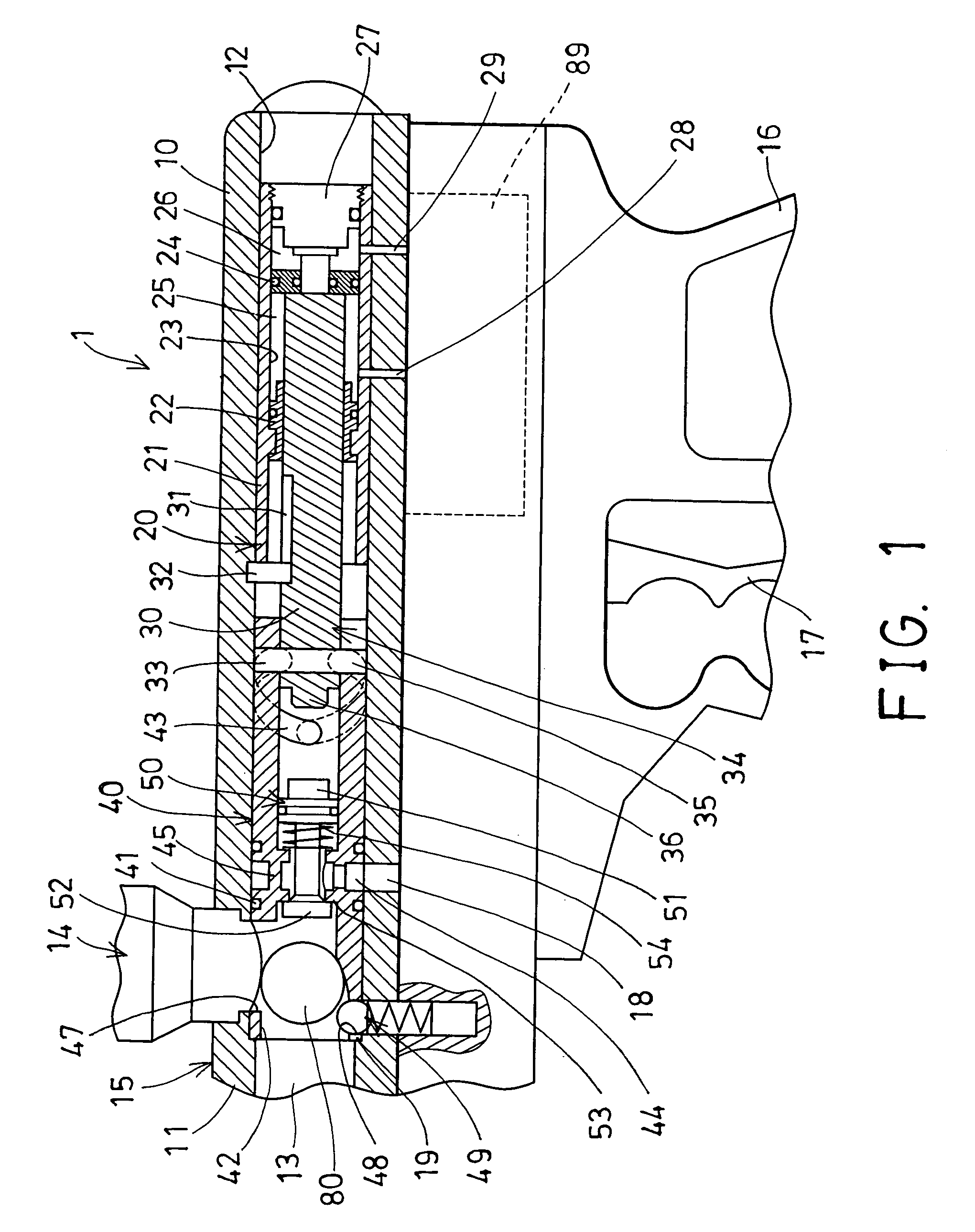
[0024]Referring to the drawings, and initially to FIGS. 1 and 4-5, a pneumatic paintball gun or bullet gun device 1 in accordance with the present invention comprises a gun body or housing 10 with a gun barrel 11 secured to and projecting from the forward end of the housing 10. The housing 10 includes a longitudinal or inner chamber 12 formed therein and a firing chamber 13 provided or formed in the front portion of the housing 10 or of the gun barrel 11 for receiving a paintball or a bullet 80 therein, and a feed tube 14 attached or coupled to the front or middle portion 15 of the housing 10 for feeding or supplying the paintball or bullet 80 into the firing chamber 13 of the housing 10 one by one.

[0025]The housing 10 further includes a hand grip or handle 16 for being held or grasped by the users, and includes a trigger 17 for being pulled or actuated by the users, and includes a gas supplying passage 18 formed therein and communicating with the inner chamber 12 of the housing 10 ...


PUM


Abstract

A gun device includes a housing having a gas supplying passage communicating with an inner chamber of the housing for coupling to a pressurized gas supplying source, a feed tube attached to the housing for feeding a bullet into the housing, a tubular member rotatably received in the housing and having an opening communicated with a bore of the tubular member for aligning with the feed tube and for selectively receiving the bullet into the bore of the tubular member. The opening of the tubular member is movable or disengageable from the feed tube when the tubular member is rotated relative to the housing for preventing the other bullet from entering into the housing.

Description

BACKGROUND OF THE INVENTION[0001]1. Field of the Invention[0002]The present invention relates to a pneumatic paintball gun, and more particularly to a pneumatic paintball gun including a simplified loading and firing mechanism for allowing the paintball or bullet to be easily and quickly loaded and to be effectively fired by pressurized air or gas.[0003]2. Description of the Prior Art[0004]Typical pneumatic paintball guns or bullet guns comprise a handgun shaped gun body including a hand grip for being held or grasped by the users, and including a loading assembly disposed in the upper portion of the gun body for feeding the paintballs or bullets into the firing chamber of the gun body one by one, and including a firing assembly disposed in the middle or lower portion of the gun body for firing the paintballs or bullets out of the firing chamber of the gun body.[0005]For example, U.S. Pat. No. 6,349,711 to Perry et al. discloses one of the typical low pressure electrically operated ...

Claims


Application Information

Patent Timeline
Patent Type & Authority Patents(United States)
IPC IPC(8): F41B11/32
CPCF41A9/45F41B11/721F41B11/73F41B11/62
Inventor GAN, YIAUGUO
Owner GAN YIAUGUO
Why Eureka
Try Eureka