System and method for internal passive cooling of composite structures

a composite structure and passive cooling technology, applied in the field of air vehicles, can solve the problems of compromising the structural integrity of the composite structure, reducing the properties of the composite, and limited use of such composites, and achieves the effects of reducing thermal loading, high speed, and cost-effectiveness

Active Publication Date: 2010-03-30
RAYTHEON CO
View PDF7 Cites 12 Cited by
  • Summary
  • Abstract
  • Description
  • Claims
  • Application Information

AI Technical Summary

Benefits of technology

[0005]Certain embodiments of the invention may provide numerous technical advantages. For example, a technical advantage of one embodiment may include the capability to reduce a thermal loading on a surface of an air vehicle. Other technical advantages of other embodiments may include the capability to enable the use of cost-effective, conventional composites in high speed, high thermal loading environments.

Problems solved by technology

However, the use of such composites is limited by the composite's maximum use temperature.
For example, when a composite's resin glass transition temperature (Tg) is exceeded, the composite can char or burn, rapidly diminishing the properties of the composite and compromising the composite's structural integrity.
However, as flight speeds of air vehicles continue to increase, the temperatures induced by air friction on the composite's control surface exceed the composite's Tg.
Therefore, a conventional belief is that composites materials are not a viable option in high speed, high thermal loading environments.

Method used


Image

  • System and method for internal passive cooling of composite structures
  • System and method for internal passive cooling of composite structures

Examples


Embodiment Construction

[0010]It should be understood at the outset that although example embodiments of the present invention are illustrated below, the present invention may be implemented using any number of techniques, whether currently known or in existence. The present invention should in no way be limited to the example embodiments, drawings, and techniques illustrated below, including the embodiments and implementation illustrated and described herein. Additionally, the drawings are not necessarily drawn to scale.

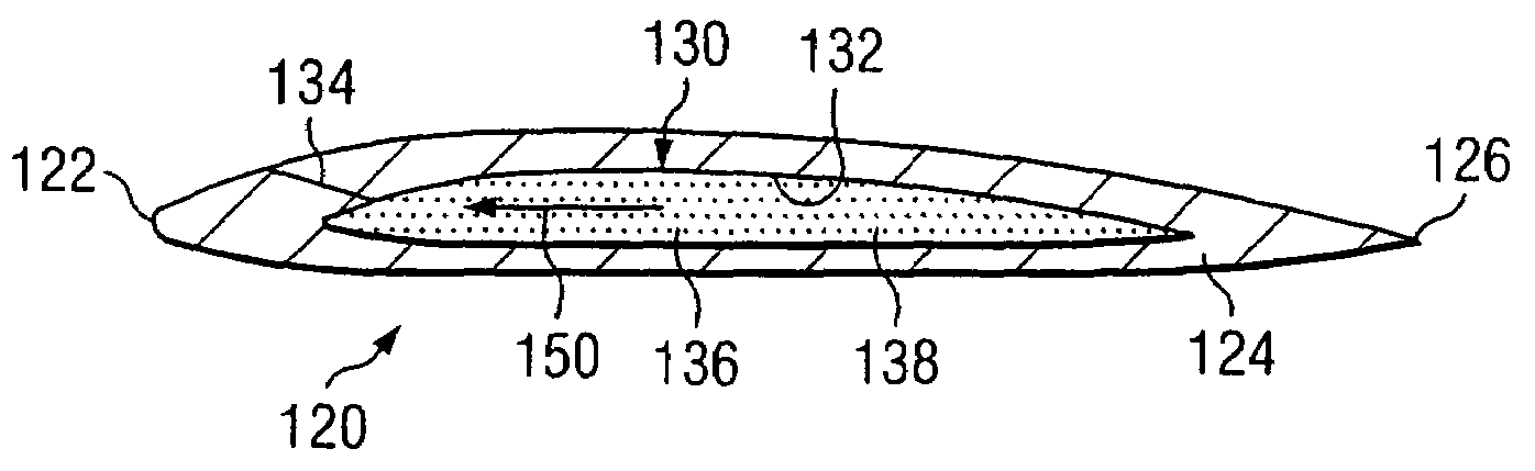
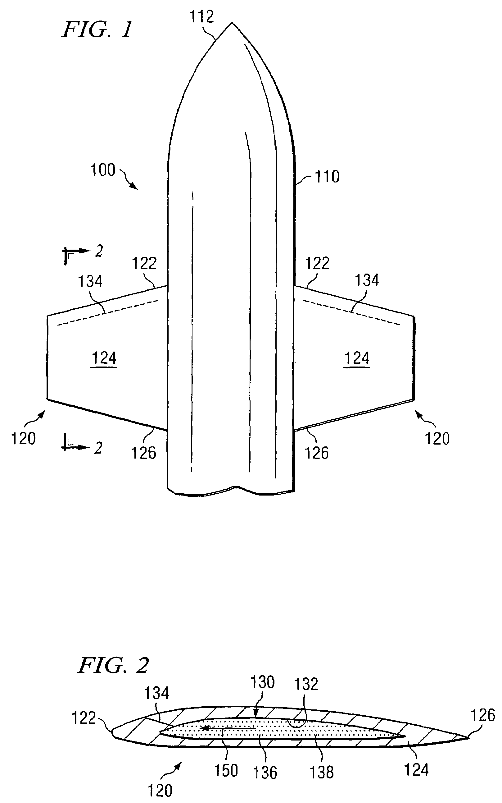
[0011]As briefly referenced in the Background, the use of composites on a control surface of an air vehicle is desirable because the composite can provide adequate strength and stiffness at a lower weight than metals. Additionally, composites are generally cheaper than ceramics designed to sustain high thermal loading. However, the use of composites in a high speed, high thermal loading environment is prohibitive because the composite's resin glass transition temperature (Tg) can be exceed...


PUM


Abstract

According to one embodiment of the invention, an apparatus comprises a passive cooling system and a portion of an air vehicle which receives thermal energy. The passive cooling system is disposed adjacent the portion of the air vehicle and comprises a fluid transfer chamber. A fluid transfer element and a coolant are disposed within the fluid transfer chamber. The fluid transfer element wicks a portion of the coolant towards the portion of the air vehicle. The portion of the coolant wicked towards the portion of the air vehicle absorb at least a portion of the thermal energy in a boiling heat transfer.

Description

TECHNICAL FIELD OF THE INVENTION[0001]This invention relates generally to the field of air vehicles and, more particularly, to a system and method for internal passive cooling of composite structures.BACKGROUND OF THE INVENTION[0002]The use of a composite (e.g., organic polymer resin) in an air vehicle (e.g., aircraft or missile) control surface is desirable because the composite can provide adequate strength and stiffness at a lower weight than metals. However, the use of such composites is limited by the composite's maximum use temperature. For example, when a composite's resin glass transition temperature (Tg) is exceeded, the composite can char or burn, rapidly diminishing the properties of the composite and compromising the composite's structural integrity.[0003]Current composites (e.g., organic polymer resins) are capable of surviving sustained use temperatures of up to about 650 F and can survive short exposure to much higher temperatures. However, as flight speeds of air veh...

Claims


Application Information

Patent Timeline
Patent Type & Authority Patents(United States)
IPC IPC(8): B64C1/38
CPCB64C1/38B64C3/36B64G1/58F42B10/04F42B15/34
Inventor WEBER, RICHARD M.CHEN, KEVIN W.LIGGETT, MICHAEL M.KRUMIN, ERICFOWLER, GRAY E.
Owner RAYTHEON CO
Why Eureka
Try Eureka