Method and device for positioning a workpiece

a technology for positioning workpieces and workpieces, applied in the direction of work holders, manufacturing tools, metal-working machine components, etc., can solve the problems of limited ability of workpiece holders/positioners, relatively complex joints and linkages, etc., and achieve the effect of reducing the force applied by magnets and being easy to reposition

Active Publication Date: 2010-03-30
THE BOEING CO
View PDF8 Cites 55 Cited by
  • Summary
  • Abstract
  • Description
  • Claims
  • Application Information

AI Technical Summary

Benefits of technology

[0005]In accordance with one aspect of the invention, a device is provided for positioning an object such as a part, comprising a body for mounting the object on the device; an array of magnets carried on the body and spatially arranged form at least a partial socket; a ball at least partially rotatable within the socket and formed of a material magnetically attracted to the magnets; and, a compressed air delivery system for delivering compressed air to the interface between the socket. The magnets are preferably permanent magnets spatially arranged in a spherical section, and wherein adjacent magnets have alternating north and south poles, respectively. The body may be integrally formed as by molding, with the magnets, or may be manufactured with a plurality of cavities in which the magnets are later installed. The compressed air delivery system may include one or more nozzles that introduce compressed air from a source to one or more channels formed in a surface of the body, contiguous to the socket. The introduction of compressed air into the socket reduces the force applied by the magnets to the ball, thus allowing the workpiece to be more easily repositioned.

Problems solved by technology

In the past, workpiece holders / positioners have been employed that are limited in their ability to reposition a workpiece in all possible positions that might be required by an operator.
In those cases where a complete range of motion is provided for positioning a workpiece, relatively complex joints and linkages are necessary.
However, even these prior art positioners do not always allow a workpiece to be positioned so that it is ergonomic and readily accessible by mechanics or assembly operators.

Method used


Image

  • Method and device for positioning a workpiece
  • Method and device for positioning a workpiece
  • Method and device for positioning a workpiece

Examples


Embodiment Construction

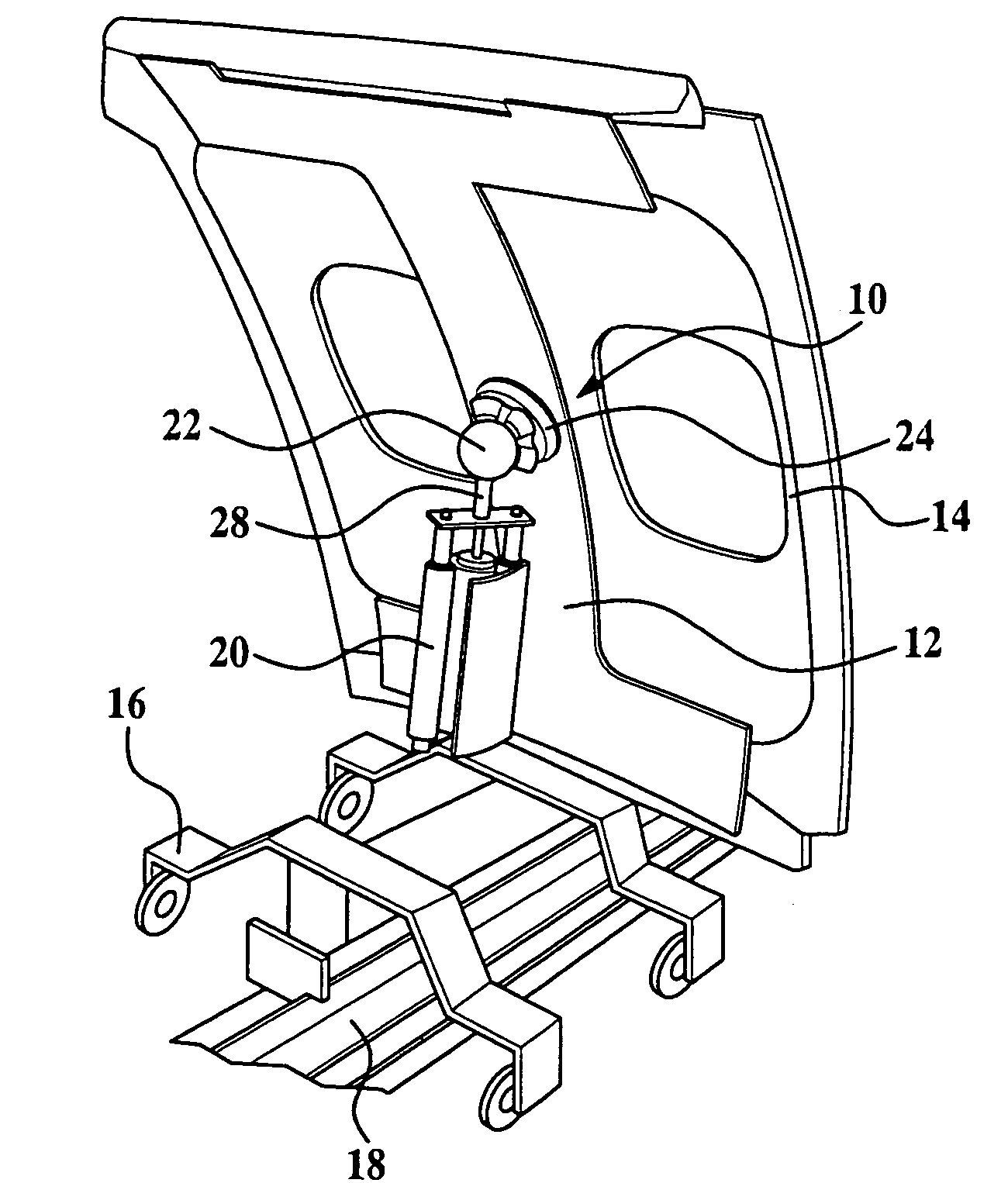
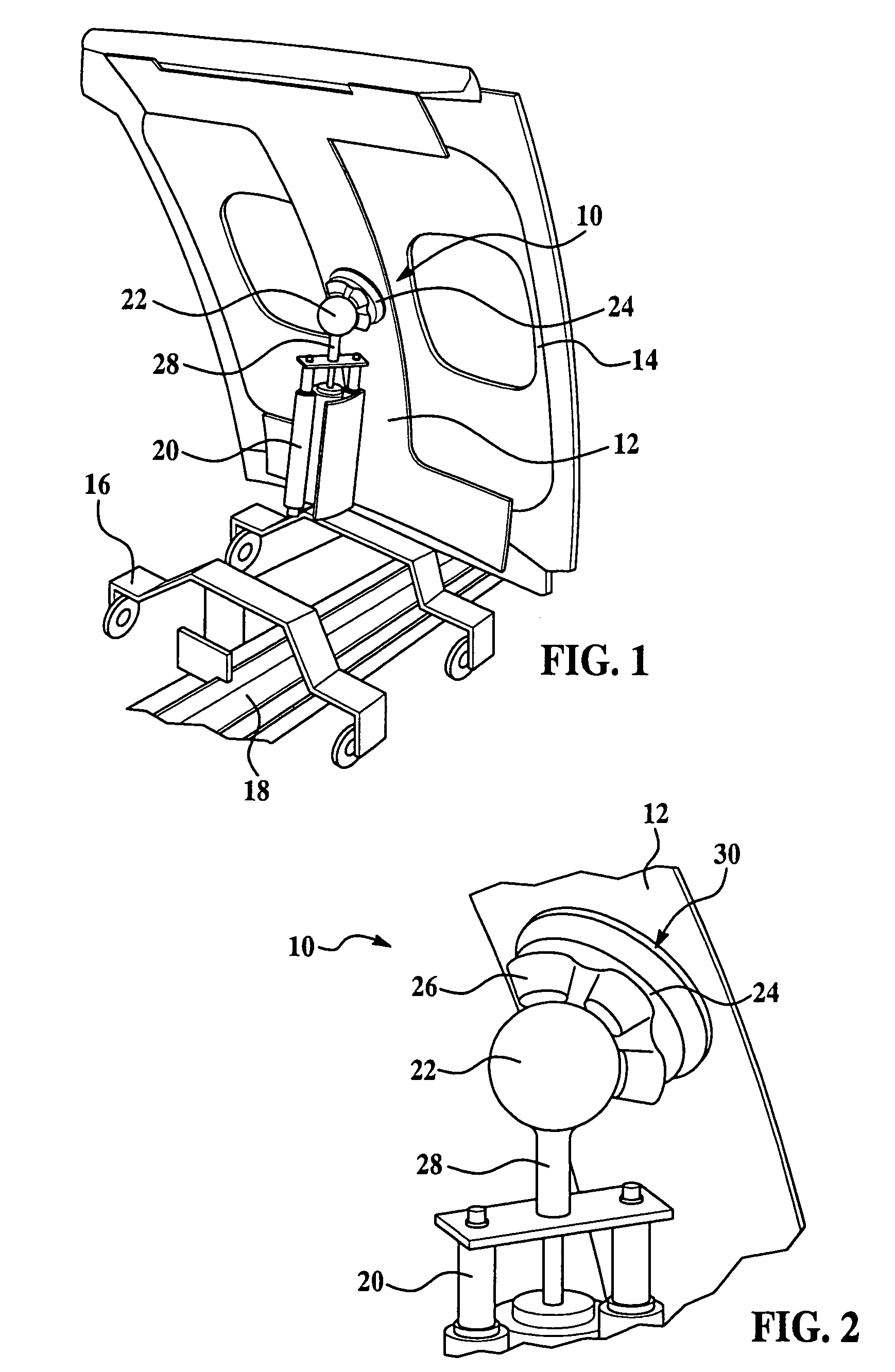
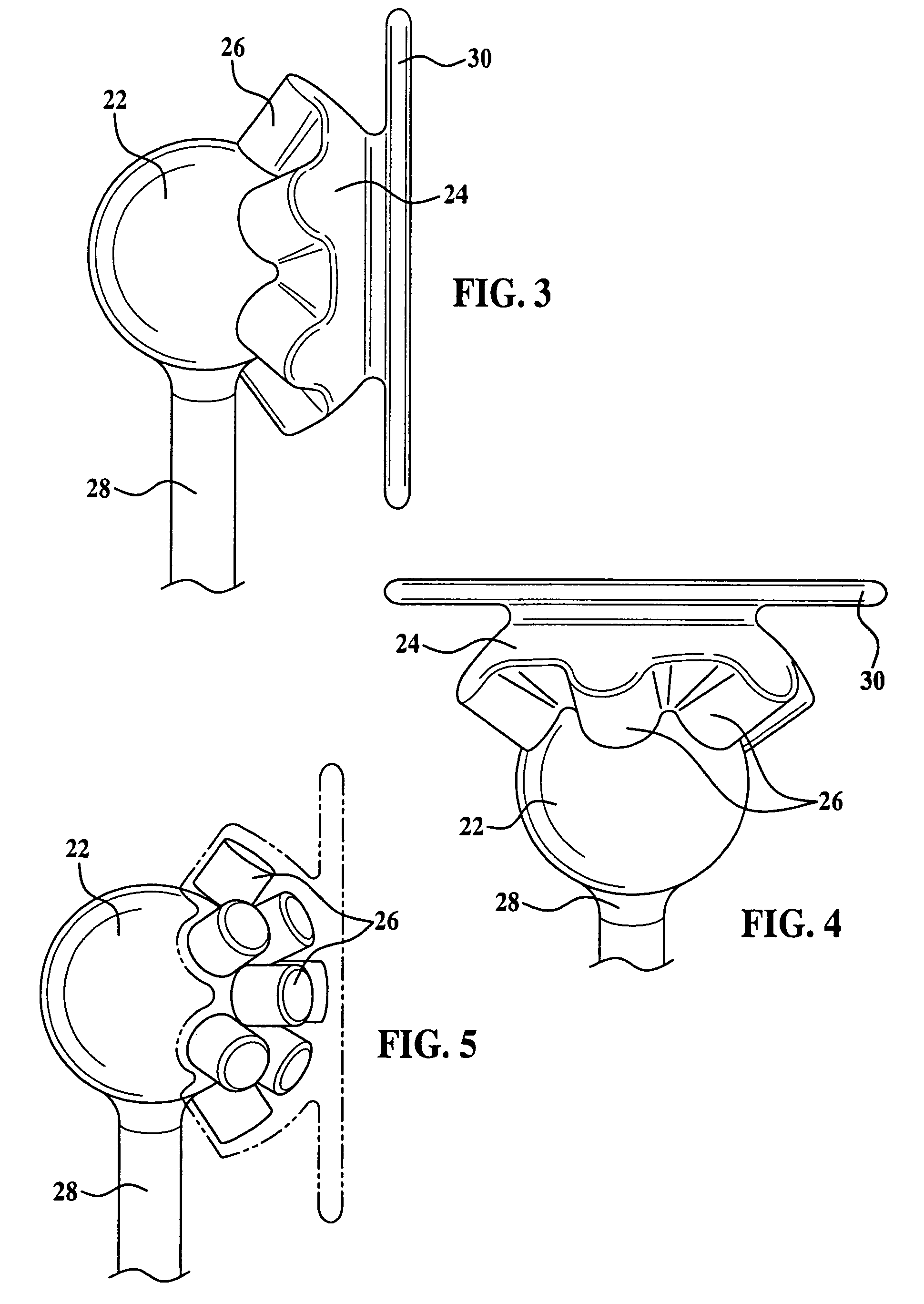
[0017]Referring first to FIG. 1, the present invention relates to an air assisted positioning device generally indicated by the numeral 10, for positioning or orienting a workpiece such as an aircraft fuselage panel 14, in any of a multiplicity of ergonomic positions to allow an assembly operator or mechanic to work on the panel 14. Broadly, the device 10 comprises a socket body 24 mounted on a ball 22 which is fixed to a support 28. In the illustrated example, the support 28 comprises the output shaft of a pneumatically operated cylinder and slide assembly 20 which controls the elevation of the panel 14. The slide assembly 20 is mounted on a wheeled trolley 16 guided along a track 18 which carries the panel 14 down an assembly line. The panel 14 is supported on a mounting fixture 12, which in turn is fixed to the socket body 24. The socket body 24, and thus the panel 14, is rotatable 180 degrees, or more around the entire surface of the ball 22, and is limited in rotational movemen...


PUM


Abstract

A device for positioning a workpiece includes a socket body rotatably held on a metallic ball by an array of permanent magnets arranged into a partial socket. An air delivery system controls a flow of air passing between the magnets and the ball to alter the friction between the socket body and the ball. A positive flow of air into the socket reduces the friction, allowing the workpiece to be more easily rotated during repositioning, whereas drawing air away from the socket produces a partial vacuum which increases the friction, causing the socket body to be locked in a single position on the ball.

Description

FIELD OF THE INVENTION[0001]The present invention broadly relates to devices for holding and positioning parts and workpieces, and deals more particularly with a method and device for positioning a workpiece using an air assisted, magnetic ball and socket.BACKGROUND OF THE INVENTION[0002]Various devices have been used in the past to hold and position objects such as parts and workpieces. Positioning devices are particularly important in manufacturing environments where a workpiece being assembled must be repositioned as a worker performs assembly or other operations on the workpiece. One example of the need for robust workpiece positioners is found in the aircraft industry where many assemblies are manufactured on manual assembly lines where workers must orient and periodically reposition a workpiece to many different positions during assembly or other operations.[0003]In the past, workpiece holders / positioners have been employed that are limited in their ability to reposition a wor...

Claims


Application Information

Patent Timeline
Patent Type & Authority Patents(United States)
IPC IPC(8): B23Q1/25B25B1/22
CPCB23Q1/32B23Q1/545B25B11/002B33Y80/00
Inventor DIXON, ROBERTBUCKMILLER, JONIRVINE, RICHARD
Owner THE BOEING CO
Why Eureka
Try Eureka