Combination of a screw member, a washer and a sleeve and also a method of producing such a combination

a technology of screw member and washer, which is applied in the direction of washers, pins, fastening means, etc., can solve the problems of only being able to achieve the retention of the washer's sleeves, and not being particularly secur

Inactive Publication Date: 2010-03-30
ELRINGKLINGER AG
View PDF24 Cites 21 Cited by
  • Summary
  • Abstract
  • Description
  • Claims
  • Application Information

AI Technical Summary

Benefits of technology

[0006]The object of the present invention is to provide a combination of the type mentioned hereinabove which is producible in a simple manner but which nevertheless ensures that the sleeve and the washer are held securely on the screw member.
[0011]The hold between the sleeve and the washer pressed thereagainst is thereby improved.
[0015]In order to enable the washer to rest on the screw head of the screw member, it is of advantage if the at least one projection is arranged at a screw head end of the sleeve.
[0016]In a preferred embodiment of the invention, provision is made for the regions of the washer bounding the at least one recess which may, in particular, be in the form of webs, to be oriented substantially perpendicularly to the longitudinal axis of the sleeve when in the state where it is pressed against the sleeve. The effect is thereby achieved that the washer is substantially flat in the state where it is pressed against the sleeve.
[0023]The further object of the present invention is to provide a method of producing such a combination which can be carried out in a simple manner but which nevertheless leads to the sleeve and the washer being held securely together and held securely on the screw member.

Problems solved by technology

The retention of the sleeve on the washer, which is only being accomplished by the clamping effect of the collar projecting into the sleeve, is not particularly secure.

Method used


Image

  • Combination of a screw member, a washer and a sleeve and also a method of producing such a combination
  • Combination of a screw member, a washer and a sleeve and also a method of producing such a combination
  • Combination of a screw member, a washer and a sleeve and also a method of producing such a combination

Examples


Embodiment Construction

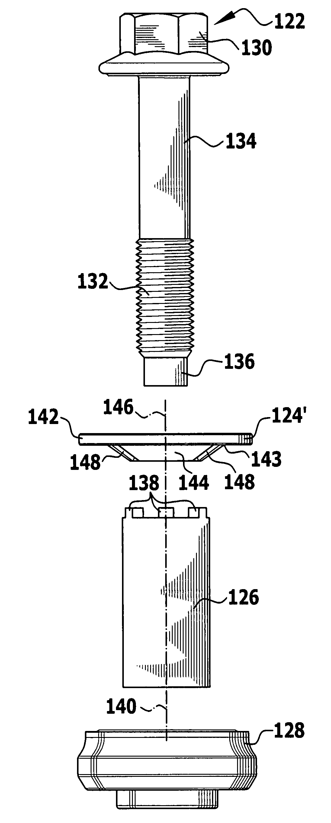
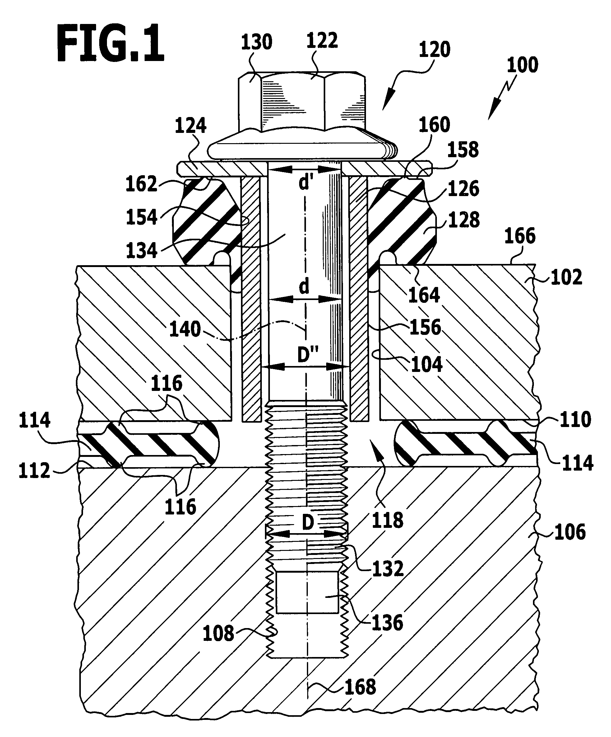
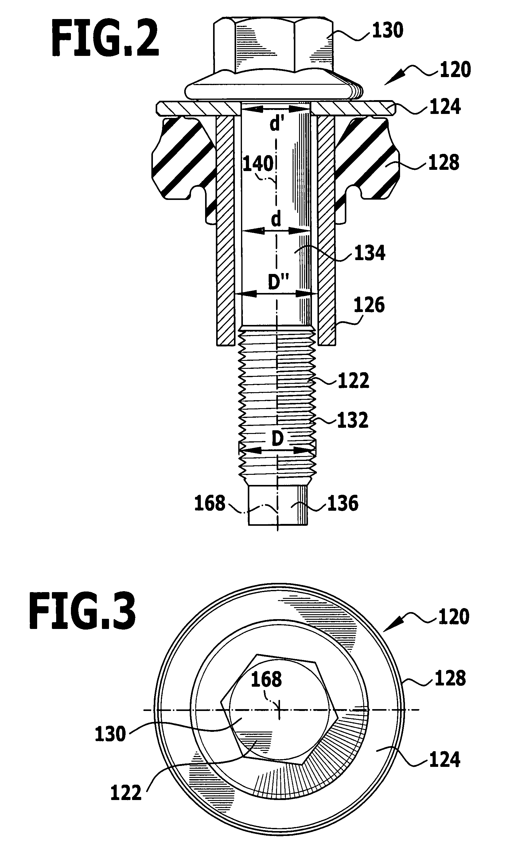
[0039]An assembly having the general reference 100 which is illustrated in sectional manner in FIG. 1 comprises a first component 102 having a substantially cylindrical passage opening 104, a second component 106 having a threaded blind hole 108, an elastomer sealing element 114 comprising sealing lips 116 that is arranged between a lower surface 110 of the first component 102 and an upper surface 112 of the second component 106 and has a passage opening 118 in the vicinity of the threaded blind hole 108, and also a combination 120 consisting of a screw member 122, a washer 124 held captive on the screw member 122, a hollow cylindrical sleeve 126 held captive on the screw member 122 and a ring-shaped element 128 surrounding the screw head end portion of the sleeve 126 in ring-like manner.

[0040]The screw member 122 comprises a screw head 130 which may be in the form of a hexagonal screw head for example, a threaded portion 132 having an external diameter D, a shank portion 134 which ...


PUM

PropertyMeasurementUnit
angleaaaaaaaaaa
angleaaaaaaaaaa
diameteraaaaaaaaaa

Abstract

In order to produce a combination of a screw member comprising a screw head, a threaded portion and a shank portion which is arranged between the screw head and the threaded portion and has an external diameter that is smaller than the external diameter of the threaded portion, a washer incorporating a passage opening the diameter of which is smaller than the external diameter of the threaded portion, and a sleeve the internal diameter of which is greater than the external diameter of the threaded portion, whereby said combination can be produced in a simple manner but nevertheless ensures that the sleeve and the washer are held securely on the screw member, it is proposed that the sleeve have at least one projection which engages in a recess provided in the washer, wherein the sleeve is pressed against the washer in such a manner that the sleeve and the washer are connected together and held captive on the screw member.

Description

[0001]This application is a continuation of International application No. PCT / EP2006 / 010070 filed on Oct. 19, 2006.RELATED APPLICATION[0002]The present disclosure relates to the subject-matter which was disclosed in the international patent application No. PCT / EP2006 / 010070 dated Oct. 19, 2006. The entire description of this earlier application is incorporated by reference thereto as a constituent part of the present description (“incorporation by reference”).FIELD OF DISCLOSURE[0003]The present invention relates to a combination of a screw member comprising a screw head, a threaded portion and a shank portion which is arranged between the screw head and the threaded portion and has an external diameter that is smaller than the external diameter of the threaded portion,a washer incorporating a passage opening the diameter of which is smaller than the external diameter of the threaded portion, and a sleeve the internal diameter of which is greater than the external diameter of the th...

Claims


Application Information

Patent Timeline
Patent Type & Authority Patents(United States)
IPC IPC(8): F16B21/18
CPCF16B43/00F16B41/002F16B17/006Y10T29/49948
Inventor AMANN, ERICHBOHRINGER, PETER
Owner ELRINGKLINGER AG
Why Eureka
Try Eureka