Electrical connector configured by unit section

a technology of electrical connectors and unit sections, applied in the direction of electrical equipment, coupling contact members, printed circuits, etc., can solve the problems of difficult mold mold, insulating material cannot be filled, and the housing is difficult to mold

Inactive Publication Date: 2010-03-30
HON HAI PRECISION IND CO LTD
View PDF4 Cites 12 Cited by
  • Summary
  • Abstract
  • Description
  • Claims
  • Application Information

AI Technical Summary

Benefits of technology

[0010]Accordingly, an object of the present invention is to provide an electrical connector for increasing the number of the contacts thereof.

Problems solved by technology

In addition, when an industry trend is to obtain highest quantity of contacts on the electrical connector, the housing of the electrical connector needs receive more terminals therein for getting a better electrical connection and transmitting more signals, so much passageways are formed on the housing, correspondingly that leads the housing difficultly to mold, such as insulative material can not fill fully of moulds.
However, previous attempts in forming higher density electrical connector met much difficulties resulted from uneven distribution of material flow and shrinkages, problems that were magnified as the housing / array of the contacts became larger.
The electrical connector disclosed by Brodsky or Glen Ellyn is a good concept but not a most suitable way.
Moreover, the electrical connector also needs a frame for fixing the sections to be a unitary structure, thus it is more complicated to manufacture the electrical connector.

Method used


Image

  • Electrical connector configured by unit section
  • Electrical connector configured by unit section
  • Electrical connector configured by unit section

Examples


Embodiment Construction

[0016]A preferred embodiment of the present invention will be described hereunder with reference to the accompanying drawings FIG. 1-FIG. 3.

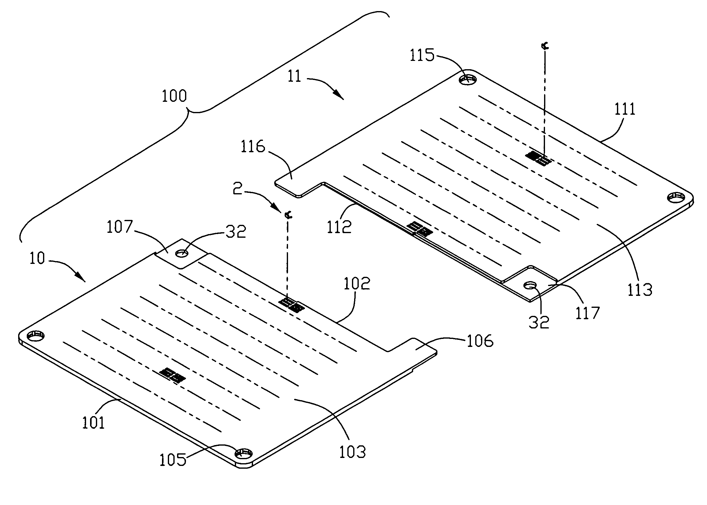
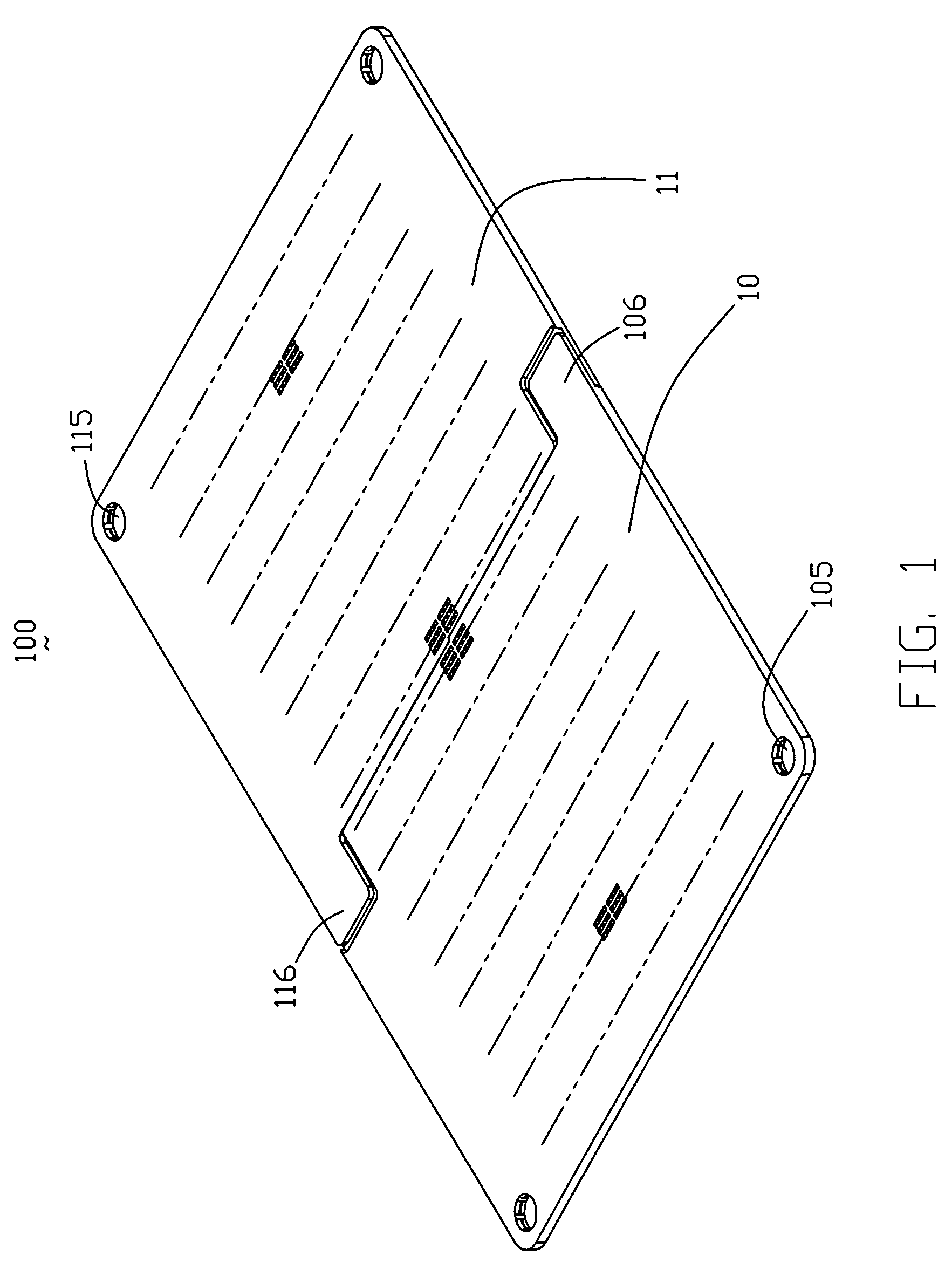
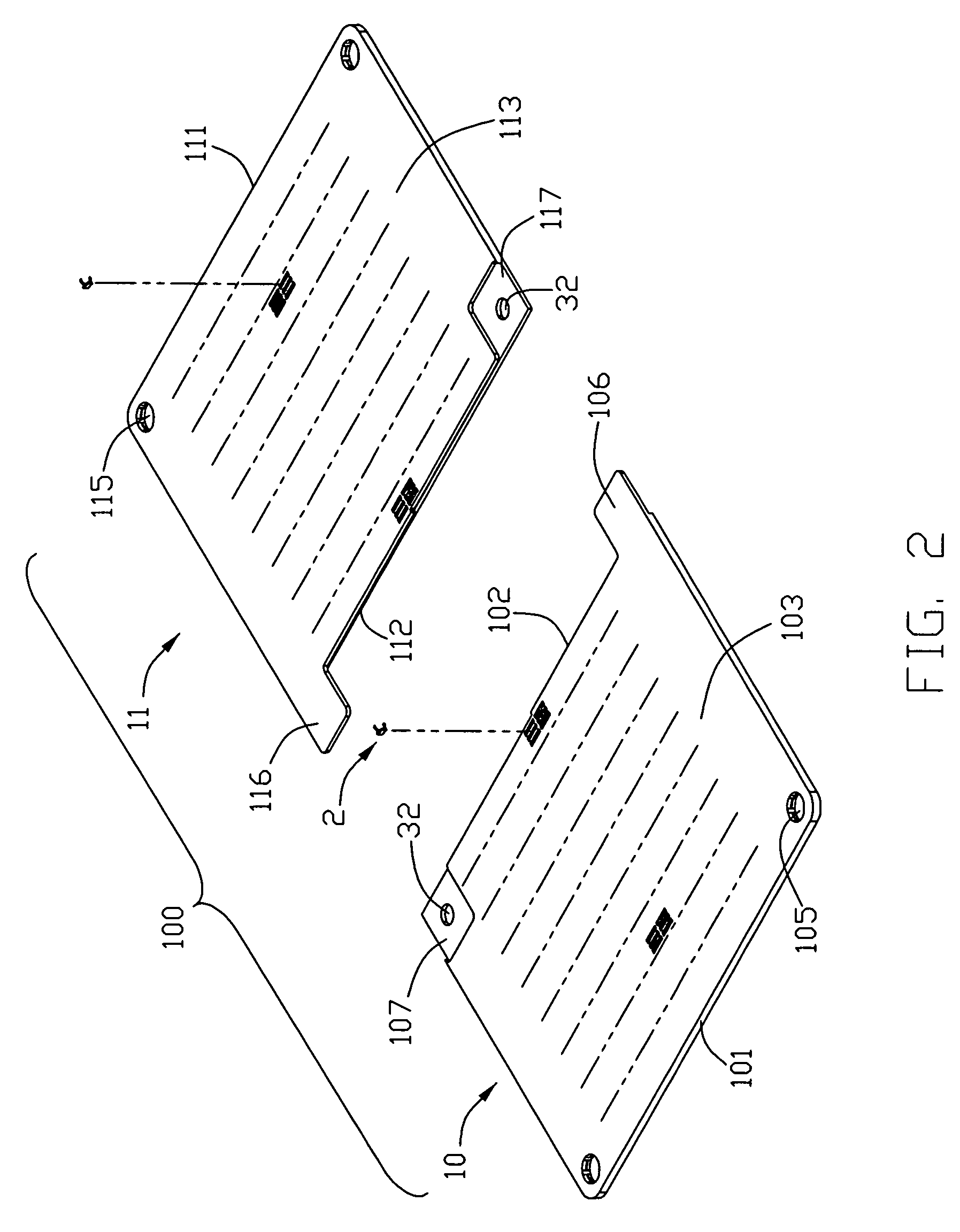
[0017]Referring to FIGS. 1 and 2, an electrical connector 100, for electrically interconnecting an integrated circuit (IC) package (not shown) with a printed circuit board (PCB) (not shown), according to the present invention is shown. As depicted, the electrical connector 100 includes two unit sections 10 and 11. Each unit section 10, 11 receives a plurality of terminals 2.

[0018]Referring now to FIGS. 2-4 the unit sections 10, 11 are configured a substantially rectangular shape and are formed from one mold. The unit section 11 includes a fixing edge 101, an opposite engaging edge 102, a mating surface 103 and an opposed surface 104. A plurality of passageways 108 are disposed through the mating surface 103 to the mounting surface 104 for accommodating the terminals 2, respectively. The fixing edge 101 defines two through holes 105 at two ends t...


PUM


Abstract

An electrical connector for electrically connecting an integrated circuit package to a circuit substrate includes a first and a second unit sections, and each unit section has a number of terminals received therein. Each unit section includes a mating surface, an opposed mounting surface, a fixing edge, and an engaging edge. The engaging edge of the first unit section has a protruding tongue, and the engaging edge of the second unit section defines a recessed portion for engaging the protruding tongue. An interlocking device is formed between the protruding tongue and the recessed portion, so that the protruding tongue is capable of overlapping and combined with the recessed portion via the interlocking device to make the first and the second unit sections become a unitary structure.

Description

BACKGROUND OF THE INVENTION[0001]1. Field of the Invention[0002]In general, the present invention relates to the art of electrical connectors. Specifically, the present invention provides an electrical connector configured by unit sections that are interconnected with each other by interlocking devices.[0003]2. Background of the Invention[0004]Generally, a conventional connector to which the present invention is related is interposed between a first and a second electronic parts or components having contact pads, respectively, to achieve electrical connection between the first and the second electronic components. In the following description, the first and the second electronic parts or components are a printed circuit board and a Large Scale Integrated circuit (LSI), respectively. The connector comprises an insulator provided with a plurality of contact receptacle holes penetrating the insulator in a thickness direction, and a plurality of elastic contacts and inserted into and he...

Claims


Application Information

Patent Timeline
Patent Type & Authority Patents(United States)
IPC IPC(8): H01R12/00
CPCH05K7/1069H01R13/24
Inventor LIAO, FANG-JWUCHANG, CHUN-YI
Owner HON HAI PRECISION IND CO LTD
Why Eureka
Try Eureka