Supercharge Your Innovation With Domain-Expert AI Agents!

Lighting load management system for lighting systems having multiple power circuits

a technology of lighting load management and power circuit, which is applied in the direction of instruments, light sources, electrical equipment, etc., can solve the problems of reducing the life of lamps, wasting energy, and affecting the automatic shut-off control, so as to increase the illumination of the space by lamps

Active Publication Date: 2010-03-30
SQUARE D CO
View PDF8 Cites 30 Cited by
  • Summary
  • Abstract
  • Description
  • Claims
  • Application Information

AI Technical Summary

Benefits of technology

The system minimizes energy wastage and extends lamp life by optimizing the selection of power circuits, reducing the frequency of replacements and environmental impact by ensuring lamps are replaced only when necessary, thereby lowering costs and environmental sensitivity.

Problems solved by technology

Although these methods save energy, there are some detrimental side effects to the automatic shut-off control.
If an occupancy sensor turns lights OFF long after the last occupant has left an area, energy is wasted.
If an occupancy sensor turns lights ON and OFF too frequently, the lamp life is significantly diminished.
The cost of replacing lamps, as well as the temporary loss of use for the area, is undesirable.
A great deal of effort has been expended by the manufacturers of occupancy sensors to optimize timing.
Even if timing is optimized to solve the problem of frequent cycling, another problem remains.
The costs of spot re-lamping are very high since it requires multiple service events.
Since lamps often contain toxic materials, such as mercury, disposal of useful lamps is environmentally insensitive.

Method used


Image

  • Lighting load management system for lighting systems having multiple power circuits
  • Lighting load management system for lighting systems having multiple power circuits
  • Lighting load management system for lighting systems having multiple power circuits

Examples


Embodiment Construction

[0026]Although the invention will be described in connection with certain preferred embodiments, it will be understood that the invention is not limited to those particular embodiments. On the contrary, the invention is intended to cover all alternatives, modifications, and equivalent arrangements as may be included within the spirit and scope of the invention as defined by the appended claims.

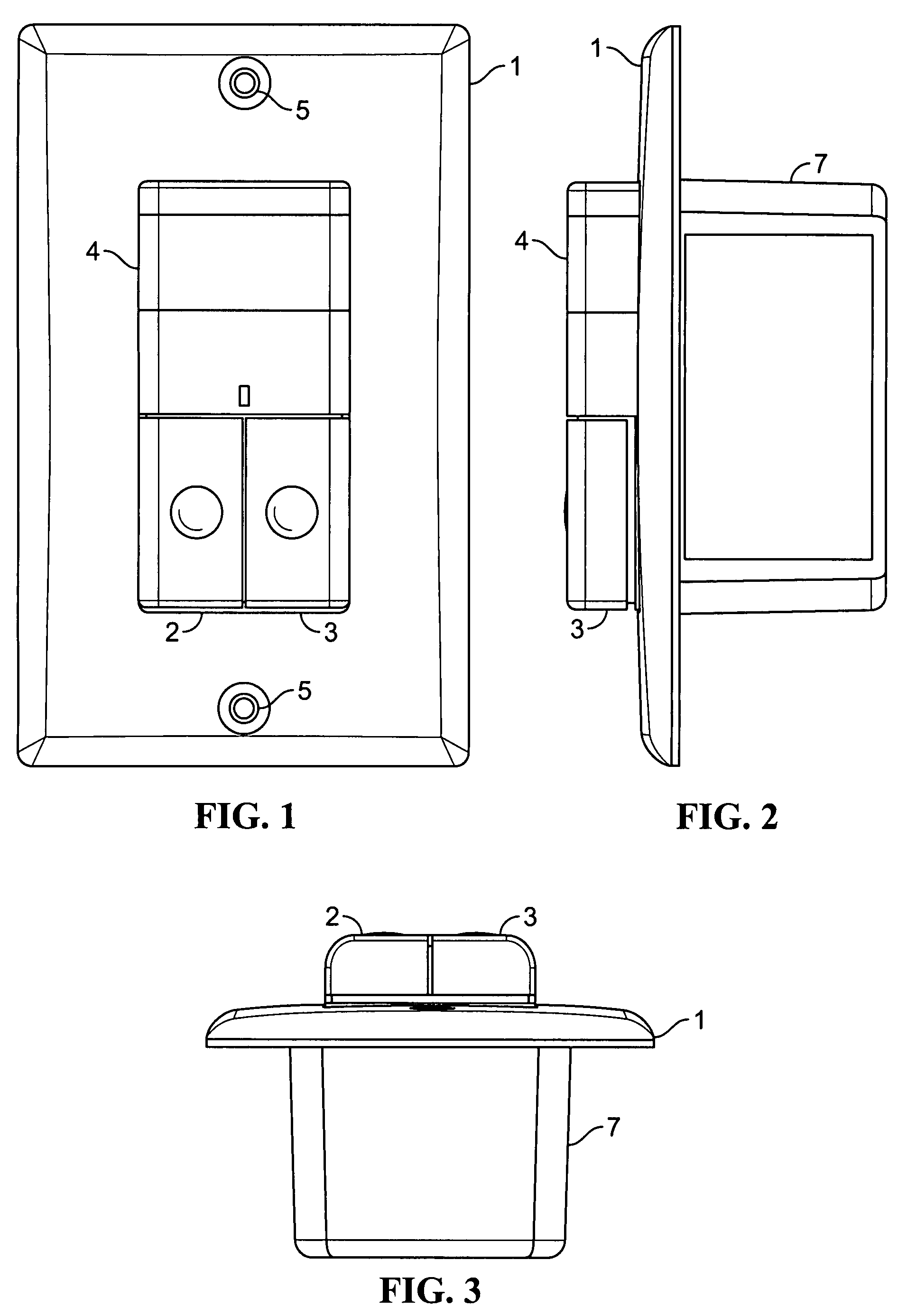
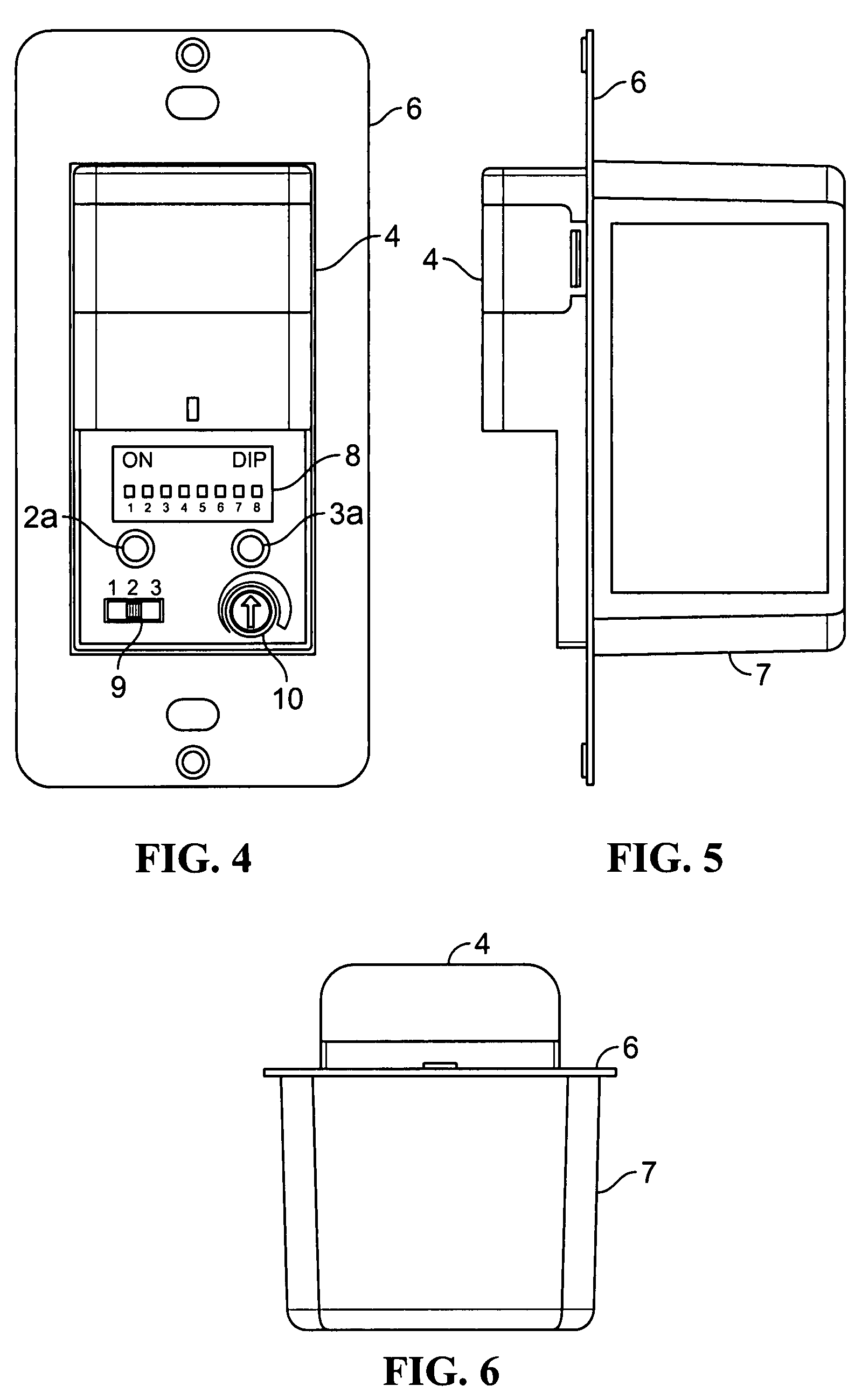
[0027]Turning now to the drawings and referring first to FIGS. 1-3, a wall plate 1 surrounds a control unit that includes a pair of pushbuttons 2 and 3 and a transparent cover 4 for the lens of a motion sensor for detecting motion within a space having artificial illumination. The plate 1 forms a pair of holes 5 for receiving a pair of screws to attach the plate 1 to a wall. FIGS. 4-6 show the same control unit shown in FIGS. 1-3 with the wall plate 1 and the covers of the pushbuttons 2 and 3 removed, revealing the underlying metal frame 6 and control unit 7. As seen most clearly in FIG. 4, th...


PUM


Abstract

A lighting control system is provided for a space that is equipped with multiple lamps for illuminating the space and multiple power circuits for supplying power to different groups of the lamps. The control system stores information relating to the past illumination of the lamps in each of the different groups. The system detects conditions or events that indicate that increased illumination of the space by the lamps is needed, and produces a control signal in response to the detection of a condition or event that indicates that increased illumination of the space by the lamps is needed. In response to the control signal, the system supplies power to at least one of the power circuits, which is selected on the basis of the stored information, to turn ON the group of lamps receiving electrical power from that power circuit.

Description

FIELD OF THE INVENTION[0001]The present invention relates to a lighting load management system for lighting systems having multiple power circuits and that automatically turn lights ON and / or OFF in response to control signals from sensors that detect whether a space is occupied or not occupied.BACKGROUND OF THE INVENTION[0002]Automatic shut-off lighting controls are used to save electrical energy, and are often required by legislated energy codes. Today's control devices have multiple control outputs which are used to operate multiple lighting circuits in a particular area. The advantage of having multiple circuits feeding an area is that multiple levels of light can be achieved by selecting the number of circuits that are ON simultaneously. This multiple-level ability is also required by some energy codes so that lower levels of artificial illumination can be provided in an occupied area.[0003]The type and arrangement of light fixtures is a factor in the application of multiple-ci...

Claims


Application Information

Patent Timeline
Patent Type & Authority Patents(United States)
IPC IPC(8): H05B41/36
CPCH05B37/02H05B37/04H05B47/29H05B47/165H05B47/17Y02B20/40
Inventor REID, DREW A.
Owner SQUARE D CO
Features
  • R&D
  • Intellectual Property
  • Life Sciences
  • Materials
  • Tech Scout
  • Unparalleled Data Quality
  • Higher Quality Content
  • 60% Fewer Hallucinations
Learn More