
Power amplifier

a power amplifier and amplifier technology, applied in the direction of gated amplifiers, amplifiers with semiconductor devices only, amplifiers with semiconductor devices, etc., can solve the problem that the switch that can turn the channel on only by applying gate voltage cannot be formed, and achieves the effect of reducing the minimum operating voltage, widening the degree of freedom in design, and reducing the impedance mismatch

Active Publication Date: 2010-03-30
MURATA MFG CO LTD
View PDF8 Cites 15 Cited by
  • Summary
  • Abstract
  • Description
  • Claims
  • Application Information

AI Technical Summary

Benefits of technology

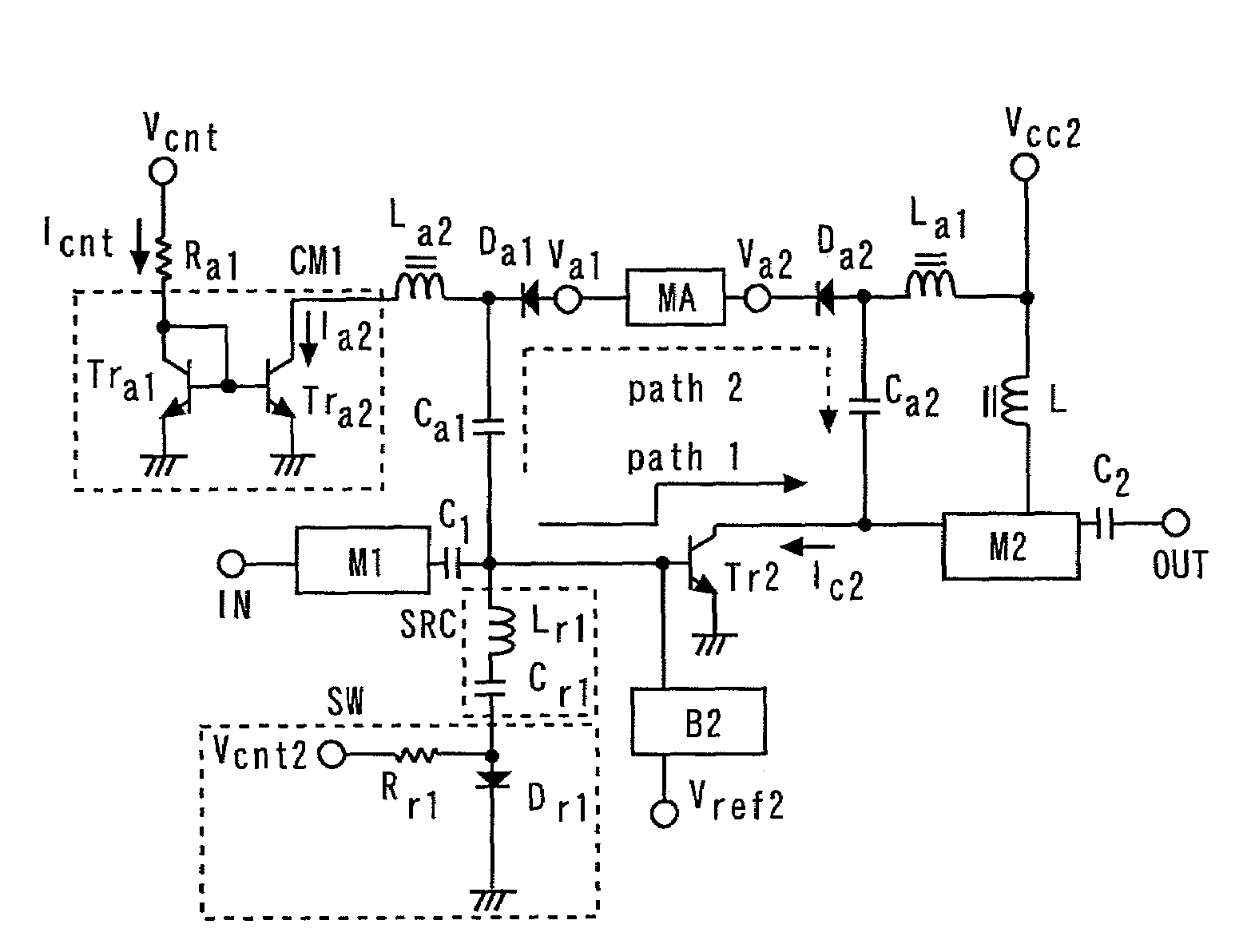
[0015]In addition to the basic configuration of the amplifier, a matching attenuation circuit MA, BC diodes Da1 and Da2, capacitors Ca1 and Ca2, inductors La1 and La2, a current mirror circuit CM1, a resistor Ra1, and a control terminal Vcnt are provided. The matching attenuation circuit MA reduces impedance mismatch between the input terminal IN side and the output terminal OUT side, and attenuates RF signals. The current mirror circuit CM1 supplies current Ia2 to the BC diodes Da1 and Da2 corresponding to reference current Icnt to drive the BC diodes Da1 and Da2.
[0018]In the circuit shown in FIG. 15, since the matching attenuation circuit MA reduces impedance mismatch between the input terminal IN side and the output terminal OUT side, impedance mismatch between input and output in the attenuation mode can be reduced. Furthermore, since the BC diodes Da1 and Da2 are turned off in the amplification mode, the effect of the bypass circuit to the power amplifier can be significantly reduced. Thereby, the power amplifier and the bypass circuit can be independently designed. In other words, the transistor size in the power amplifier or the attenuation quantity of the bypass circuit can be freely designed.
[0020]To solve the above-described problems, it is an object of the present invention to obtain a power amplifier that can lower minimum operating voltage, can reduce the impedance mismatch between input and output in the attenuation mode, can widen the degree of freedom in designing, and can suppress the degradation of distortion characteristics when a large power is inputted in the attenuation mode.
[0022]According to the present invention, a power amplifier that can lower minimum operating voltage, can reduce the impedance mismatch between input and output in the attenuation mode, can widen the degree of freedom in designing, and can suppress the degradation of distortion characteristics when a large power is inputted in the attenuation mode can be obtained.

Problems solved by technology

However, when an RF (high frequency) switch element is composed by a normal GaAs-HBT process, a switch that can turn the channel on only by applying gate voltage cannot be formed.

Method used


Image

  • Power amplifier
  • Power amplifier
  • Power amplifier

Examples


first embodiment

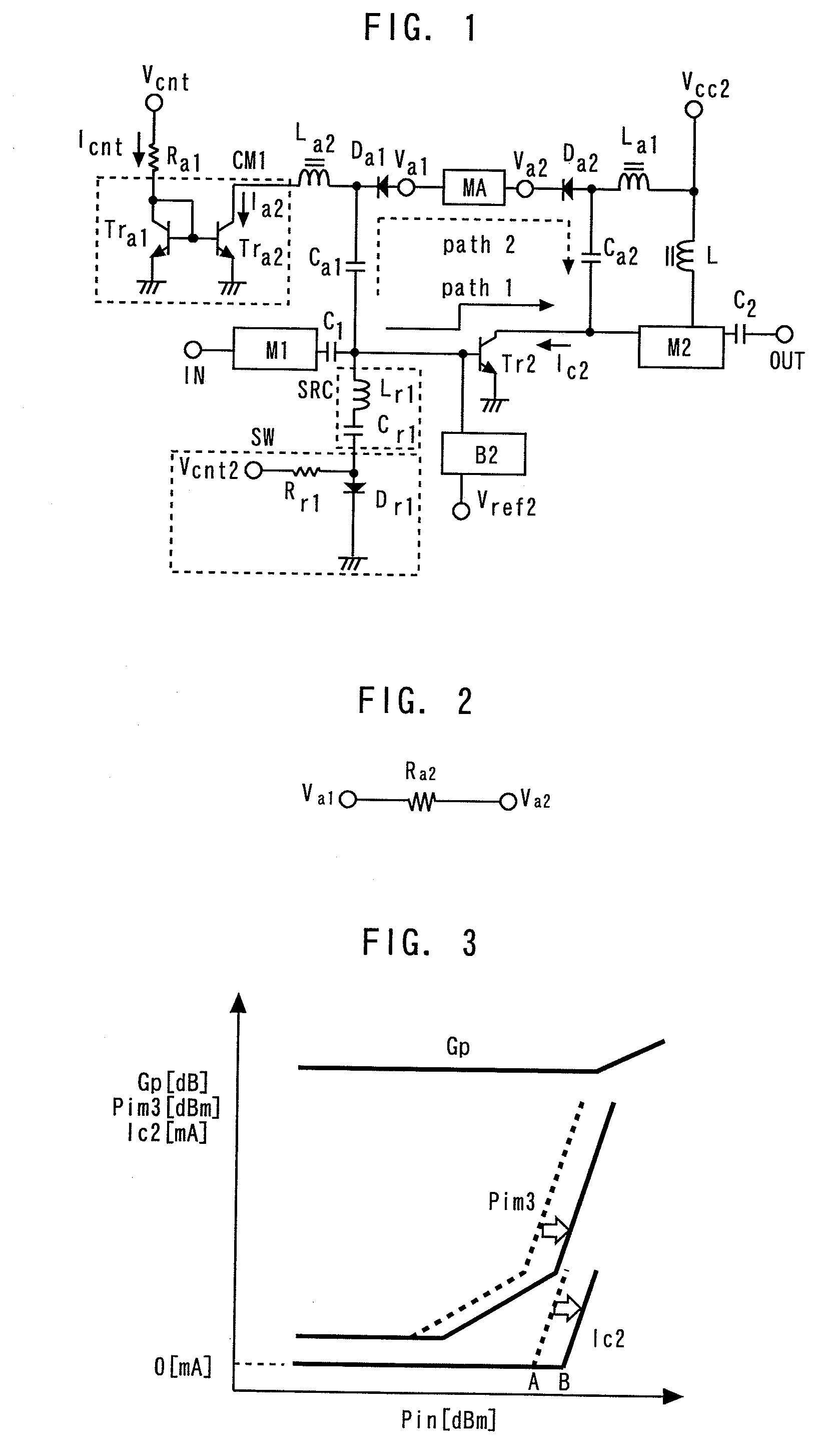
[0040]FIG. 1 is a circuit diagram showing a power amplifier according to a first embodiment of the present invention. The power amplifier is formed using a GaAs-HBT process.

[0041]The base of an amplifying transistor Tr2 that amplifies RF signals is connected to an input terminal IN via an input matching circuit M1 and a capacitor C1, the collector thereof is connected to an output terminal OUT via an output matching circuit M2 and a capacitor C2, and the emitter thereof is grounded. An inductor L is provided between a collector power terminal Vcc2 and the output matching circuit M2. A bias circuit B2 supplies bias current to the base of the amplifying transistor Tr2 corresponding to voltage applied to a control terminal Vref2.

[0042]The cathode of a BC diode Da1 (first diode) is connected to the input terminal IN via a capacitor Ca1 (first capacitor), the capacitor C1, and the input matching circuit M1. The anode of a BC diode Da2 (second diode) is connected to the output terminal OU...

second embodiment

[0059]FIG. 7 is a circuit diagram showing a power amplifier according to a second embodiment of the present invention. Components same as in the first embodiment are denoted by the same reference characters and numerals, and the description thereof will be omitted.

[0060]Other than the configuration of the switch SW, the second embodiment is identical to the first embodiment. The switch SW has a BC diode Dr1 (third diode), resistors Rr1 and Rr2, a current mirror circuit CM2 (second current mirror circuit), and a capacitor Cr2. The anode of the BC diode Dr1 is connected to a serial resonance circuit SRC. The resistor Rr2 is connected between the anode of the BC diode Dr1 and the power terminal Vcb2 of the bias circuit B2 (second power terminal). The current mirror circuit CM2 is connected to the cathode of the BC diode Dr1, and drives the BC diode Dr1.

[0061]The resistor Rr1 forms the reference current Icnt2 of the current mirror circuit CM2 corresponding to the voltage applied to the ...

third embodiment

[0064]FIG. 8 is a circuit diagram showing a power amplifier according to a third embodiment of the present invention. Components same as in the first or second embodiment are denoted by the same reference characters and numerals, and the description thereof will be omitted.

[0065]An inductor Lr1 (third inductor) and a capacitor Cr2 (third capacitor) are connected in series between a capacitor C1 and the base of an amplifying transistor Tr2. A capacitor Cr1 (fourth capacitor) is connected in parallel to the inductor Lr1. A switch SW is connected in parallel to the inductor Lr1, and connected in series to the capacitor Cr1.

[0066]The inductor Lr1 and the capacitor Cr2 compose a serial resonance circuit whose resonance frequency is set in the operating frequency band of the amplifying transistor Tr2. The inductor Lr1 and the capacitor Cr1 compose a parallel resonance circuit whose resonance frequency is set in the operating frequency band of the amplifying transistor Tr2.

[0067]The switch...


PUM


Abstract

A power amplifier includes: an amplifying transistor; a bias circuit; a first diode; a second diode; a matching attenuating circuit; a first current mirror circuit; a serial resonant circuit, and a switch. In an amplification mode, the bias circuit supplies a bias current to the amplifying transistor, and the first current mirror circuit turns off the first and second diodes, and the switch. In an attenuation mode, the bias circuit supplies no bias current to the amplifying transistor, and the first current mirror circuit turns on the first and second diodes and the switch.

Description

BACKGROUND OF THE INVENTION[0001]1. Field of the Invention[0002]The present invention relates to a power amplifier that amplifies RF signals in an amplification mode, and attenuates RF signals in an attenuation mode. More specifically, the present invention relates to a power amplifier that can lower minimum operating voltage, can reduce the impedance mismatch between input and output in the attenuation mode, can widen the degree of freedom in designing, and can suppress the degradation of distortion characteristics when a large power is inputted in the attenuation mode.[0003]2. Background Art[0004]In recent years, GaAs-HBT (hetero-junction bipolar transistor) power amplifiers have been widely used as power amplifiers for mobile phones that perform CDMA (code division multiple access) and power amplifiers for wireless LAN.[0005]Since a GaAs-HBT requires no negative gate bias voltage, the GaAs-HBT can be operated by a single power source, and can obtain more even device characteristi...

Claims


Application Information

Patent Timeline
Patent Type & Authority Patents(United States)
IPC IPC(8): H03F1/14
CPCH03F1/0261H03F3/191H03F3/72H03F2200/18H03F2200/408H03F2203/7239H03F1/32H03F1/34H03F3/213
Inventor YAMAMOTO, KAZUYAMIYASHITA, MIYO
Owner MURATA MFG CO LTD
Learn More