Railroad train monitoring system

a monitoring system and rail road technology, applied in railway auxiliary equipment, transportation and packaging, instruments, etc., can solve the problems of providing a spot check on performance, escalating to a critical level between detectors, defects only becoming apparent, etc., and increasing complexity and costs. the investment required to monitor the car

Active Publication Date: 2010-03-30
AMSTED RAIL CO INC
View PDF47 Cites 81 Cited by
  • Summary
  • Abstract
  • Description
  • Claims
  • Application Information

AI Technical Summary

Benefits of technology

[0006]This invention has the objective of providing means for continuously, while in service, monitoring the behavior and condition of the trucks, wheels and bearings of a railroad car and provide both regular assurance of proper performance and, as necessary, warning of impending or actual failure in a timely and useful manner to the operators and owners of the train whereof if forms a part.
[0010]It is a further objective of this invention to provide means for the timely analysis of measurements made during operation of the train so that the information about performance or failure can be sent in a concise manner so that there is no need for detailed measurements to be transmitted.
[0012]It is a further objective of the invention that when operating wirelessly, it can be expanded to exploit the available choices of operating frequencies (channels) to give relief from interference between the successive (adjacent) cars in a train or from other equipment operating in the same band of frequencies.

Problems solved by technology

Since some of these performance problems could lead very quickly to a catastrophic failure of the train, it is desirable to monitor and report exceptions to the locomotive or to a central data handling facility as quickly as possible.
However, while one detector can monitor many freight cars as they pass, they can only provide a spot check on performance.
It is quite possible that defects will only become apparent and escalate to a critical level between detectors.
While providing a superior solution to that provided by wayside monitors, wiring, complexity and costs increase the investment required to monitor the cars.

Method used


Image

  • Railroad train monitoring system
  • Railroad train monitoring system
  • Railroad train monitoring system

Examples


Embodiment Construction

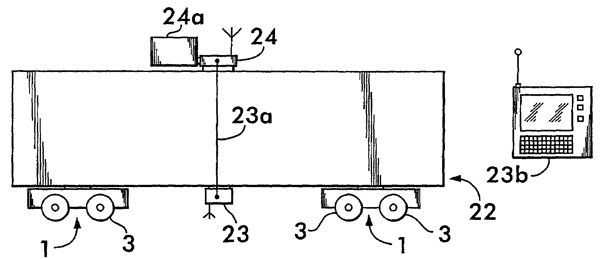
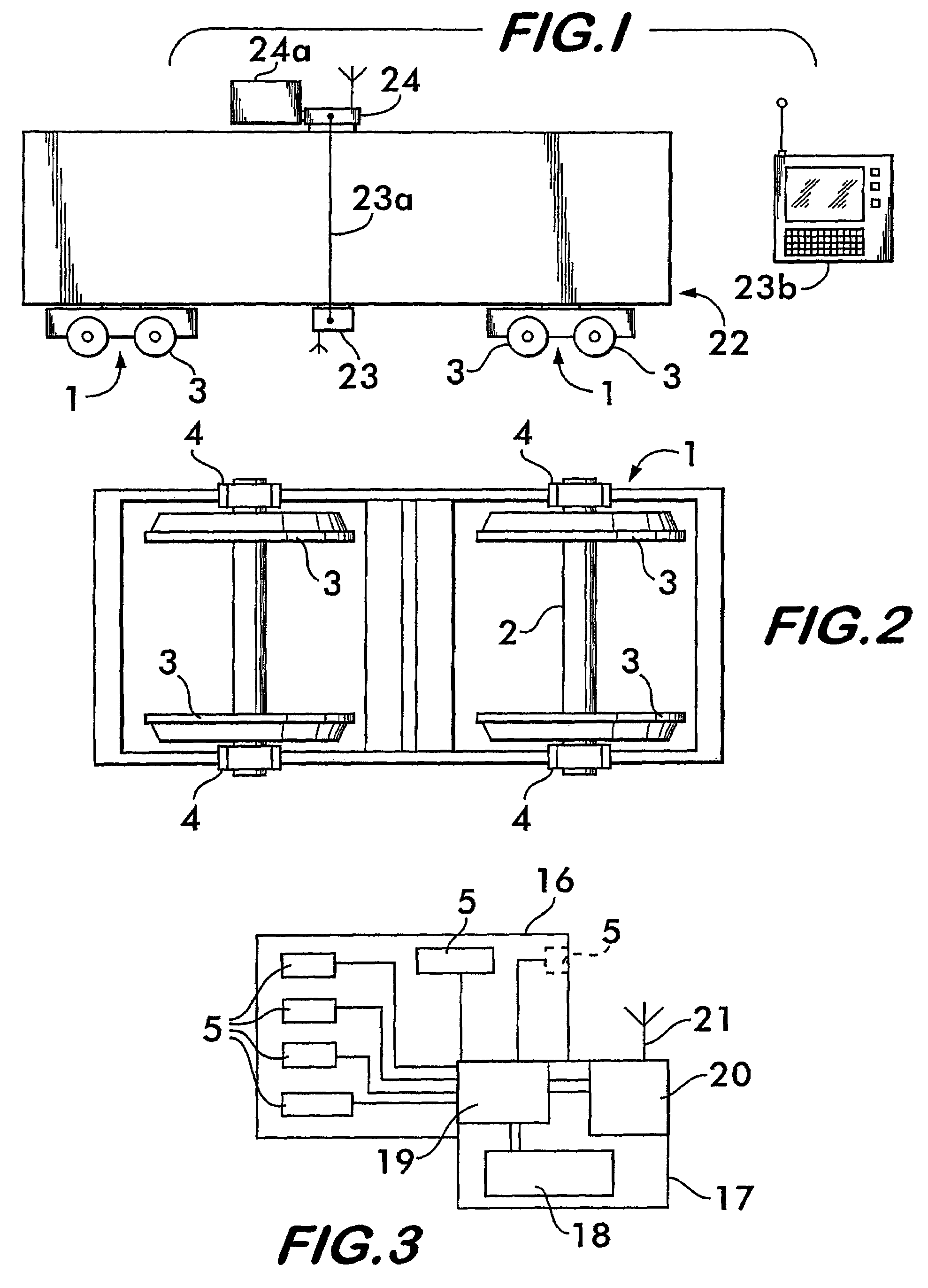
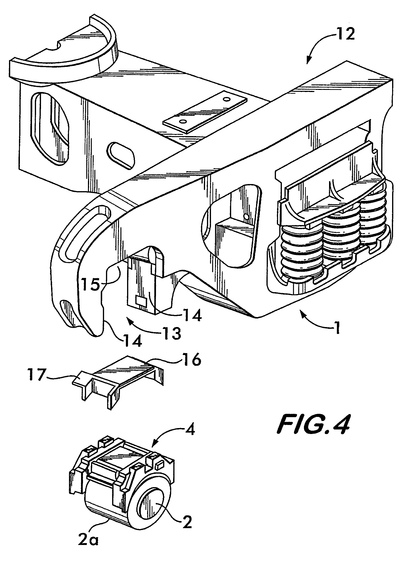
[0017]Turning now to FIGS. 1, 2 and 4, trucks 1, shown diagrammatically, each carry two axles 2 each with two wheels 3. The axle bearings 2a and bearing adapters 4, best shown in FIG. 4, are configured so that each bearing transmits the load which it carries and heat that it may generate through pads 16 and to the truck.

[0018]FIG. 4 illustrates a portion of a railcar truck 1 showing the relationship of an instrumented pad 16 relative to other truck parts. In FIG. 4, one end of a truck side frame 12 is shown. Each side frame has a pair of downwardly extending pedestal jaws 13. Parallel side walls 14 of each pedestal jaw along with a roof section 15 combine to form a pedestal jaw opening.

[0019]The truck also includes bearing adapters 4, one of which is shown in FIG. 4. The adapters have a generally rectangular upper surface with depending legs extending from the corners of the top structure. The legs have facing curved side surfaces which are configured so as to rest on the outer surf...


PUM


Abstract

Railcar monitoring utilizes instrumented, flexible pads supported within the truck pedestal jaws on the bearing adapters. The pads contain sensors for monitoring temperature pressure, shifting loads, truck hunting and the like and have circuitry for processing information received from the sensors and for processing and reporting departures of performance variables to a remote source. The system cyclically activates polling each pad on a car and communicates signals of critical departures and car identity to a remote source.

Description

FIELD OF THE INVENTION[0001]This invention relates to a monitoring system for railroad trains and the like, and more particularly a system that uses an instrumented roller bearing adapter pad to detect the occurrence and cause of poor performance at wheel set, truck, freight car or train level.BACKGROUND OF THE INVENTION[0002]More than ever, railcar owners and operators need a better understanding of how their assets are performing. With heavier cars in service, there is a greater need to identify “bad actors” (cars which can damage track infrastructure and lead to derailments) as soon as their performance becomes unacceptable. There is also a need to increase average train speed by improving high speed performance and reducing unplanned service interruptions through mechanical failures. Car owners increasingly seek to implement preventative maintenance programs to avoid mechanical failures and schedule repairs at a facility and time of their choice. Finally, with more automation of...

Claims


Application Information

Patent Timeline
Patent Type & Authority Patents(United States)
IPC IPC(8): G08B21/00
CPCB61K9/00B61L15/0072B61L25/021B61L25/025B61K13/00B61L15/0081B61L27/0077Y02T90/16B61L2205/04B60L2200/26B61L27/40B61L23/04
Inventor LEFEBVRE, WILLIAMMCCANN, MICHAEL J.
Owner AMSTED RAIL CO INC
Why Eureka
Try Eureka