Broadcast receiver with selective scanning and signal retrieval

a receiver and selective scanning technology, applied in the field of broadcast receivers, can solve the problems of not being able to receive airwaves of broadcast stations located in directions in which the antenna is not directed, and not being able to achieve optimal methods

Inactive Publication Date: 2010-03-30
FUNAI ELECTRIC CO LTD
View PDF15 Cites 4 Cited by
  • Summary
  • Abstract
  • Description
  • Claims
  • Application Information

AI Technical Summary

Benefits of technology

[0012]Also, in the invention, there may be provided a storage unit for storing reception sensitivity of airwaves every channel. In this case, the control unit reads the reception sensitivity corresponding to a channel at the time when impossibility of reception occurs out of the storage unit, and selects optimum signal return processing from among plural signal return processing based on the reception sensitivity. As a result of this, the return processing with high accuracy according to the reception sensitivity can be performed.
[0016]According to the invention, when impossibility of reception occurs in a directional switching antenna, a receivable direction can be detected efficiently, so that a return to a normal reception state can be made speedily.

Problems solved by technology

As a result of that, when an antenna is directed at one place and is fixed, airwaves of the broadcast station located in a direction in which the antenna is directed can be received, but airwaves of the broadcast station located in a direction in which the antenna is not directed cannot be received.
However, in this method, possibility or impossibility of reception for all the directions is searched, so that accuracy of retrieval is high, but it often takes time to perform the signal return and in all the cases, the method is not necessarily an optimum method.

Method used


Image

  • Broadcast receiver with selective scanning and signal retrieval
  • Broadcast receiver with selective scanning and signal retrieval
  • Broadcast receiver with selective scanning and signal retrieval

Examples


Embodiment Construction

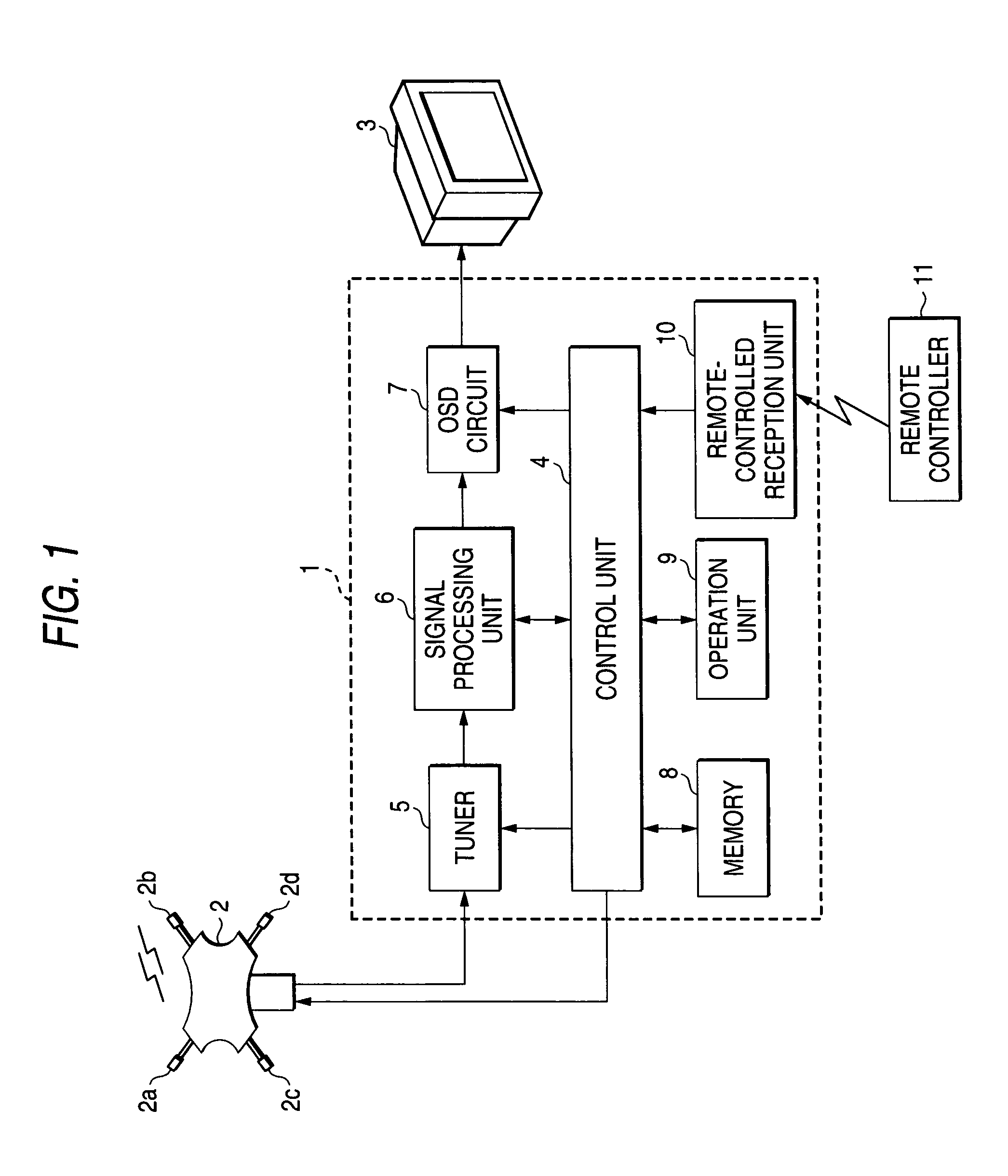
[0029]FIG. 1 is a diagram showing a receiving system of a television broadcast using a broadcast receiver according to the invention. In FIG. 1, numeral 1 is a broadcast receiver, and numeral 2 is a smart antenna, and numeral 3 is a television image receiving apparatus (hereinafter called “TV set”). The broadcast receiver 1 and the TV set 3 are installed inside a house of a general home and are connected by a cable. The smart antenna 2 is attached and fixed to a roof or a veranda of the house and is connected to the broadcast receiver 1 by a cable.

[0030]The smart antenna 2 includes four antenna elements 2a to 2d, and phase shifters, combination devices and control circuits, etc. (the portions other than the antenna elements 2a to 2d are omitted in the drawing) disposed corresponding to each of the antenna elements 2a to 2d, and directivity is electrically switched in 16 directions by adjusting phases of signals received by each of the antenna elements 2a to 2d through each of the ph...


PUM


Abstract

A broadcast receiver for receiving airwaves by a directional switching antenna capable of switching directivity in a plurality of directions, includes a control unit for performing signal return processing for making a return to a normal reception state when it becomes impossible to receive the airwaves by the antenna. The signal return processing includes a plurality of signal return processings of different kinds. When impossibility of reception occurs, the control unit selects optimum signal return processing from among the plurality of signal return processings according to predetermined conditions and executes the selected signal return processing.

Description

BACKGROUND OF THE INVENTION[0001]1. Field of the Invention[0002]The present invention relates to a broadcast receiver for receiving airwaves of a predetermined channel sent from plural broadcast stations by a directional switching antenna.[0003]2. Description of the Related Art[0004]In Japan, airwaves of television broadcasts etc. are generally sent from a base station of one place. As a result of that, almost all the airwaves sent by plural broadcast stations can be received by directing an antenna for broadcast receiving to the base station and fixing the antenna to a roof or a veranda, etc. of a house and connecting the antenna to a broadcast receiver through a cable. On the other hand, for example, in the U.S.A., airwaves are individually sent from plural broadcast stations, respectively. As a result of that, when an antenna is directed at one place and is fixed, airwaves of the broadcast station located in a direction in which the antenna is directed can be received, but airwav...

Claims


Application Information

Patent Timeline
Patent Type & Authority Patents(United States)
IPC IPC(8): H04H20/71H04B7/10H04B1/18H04N5/44
CPCH01Q3/24
Inventor ONOMATSU, TAKEHIRONARITA, SHUSUKE
Owner FUNAI ELECTRIC CO LTD
Why Eureka
Try Eureka