Supercharge Your Innovation With Domain-Expert AI Agents!

Data output method, data output apparatus and computer program product

a data output and data technology, applied in the field of data output methods, data output apparatuses and computer program products, can solve the problems of constant reproduction delay corresponding to buffer capacity, jitter in arrival delay time, and increase the delay from the arrival of a packet to the output of a packet, so as to reduce the influence of jitter in the transfer time, reduce the occurrence of constant delay, and reduce the effect of constant delay

Inactive Publication Date: 2010-03-30
FUJITSU LTD
View PDF18 Cites 1 Cited by
  • Summary
  • Abstract
  • Description
  • Claims
  • Application Information

AI Technical Summary

Benefits of technology

This approach reduces the occurrence of constant delay and sound interruptions, ensuring high-quality communication by optimizing buffer settings according to data accumulation and discarding patterns, thereby maintaining stable voice output in VoIP systems.

Problems solved by technology

However, in the communication through the IP network, since the arrival delay time required for transferring packets from the apparatus at the transmitting end to the apparatus at the receiving end varies depending on each packet, there is a problem of jitter.
The jitter in the arrival delay time is a serious problem for IP telephony that is required to perform real-time and continuous communication.
When outputting voice using the jitter buffer in such a manner, the larger the accumulation capacity of the jitter buffer for accumulating packets, the greater the ability of absorbing the jitter in the arrival delay time, but there is a problem that the delay from the arrival of a packet to the output of the packet becomes larger.
However, the method of measuring the arrival time intervals of packets as disclosed in the Japanese Patent Application Laid-Open No. 2003-87317 has problems that a device for measuring the arrival time is required, and the method depends on the assumption that the data amount transmitted from the transmitting end and the data amount received and reproduced at the receiving end are equal.
Therefore, for example, when the data amount transmitted from the transmitting end in a predetermined period is larger than the data amount reproduced at the receiving end, data reproduction at the receiving end cannot catch up with the transmission of data and the buffer is always in an overflow state, and consequently reproduction delay corresponding to the buffer capacity occurs constantly, namely a constant delay occurs.
In this case, even when the data exceeding the buffer capacity is discarded after elapse of a predetermined time, the problem of constant delay mentioned above cannot be solved.
In other words, with the prior art, the buffer capacity intended to be used for absorbing the transmission delay jitter is reduced due to the difference between the transmitted data amount and the reproduced data amount, and causes a problem that there is always a reproduction delay corresponding to the buffer capacity, more specifically the time required for reproducing the data amount corresponding to the buffer capacity.
Further, in the above-described prior art, when data exceeding the buffer capacity is discarded, there arises a problem that sound interruption occurs due to shortage of data.
This problem also occurs in the above-mentioned Japanese Patent Application Laid-Open No. 2005-136742 because when the constant delay is detected, the upper accumulation limit of the jitter buffer is always decreased irrespective of the details of the past data accumulation, and therefore the frequency that the accumulated amount of data exceeds the upper accumulation limit of the jitter buffer by the subsequent reception of data increases.
As a result, the frequency of discarding the data exceeding the upper accumulation limit increases, and sound interruption tends to occur.

Method used


Image

  • Data output method, data output apparatus and computer program product
  • Data output method, data output apparatus and computer program product
  • Data output method, data output apparatus and computer program product

Examples


embodiment 1

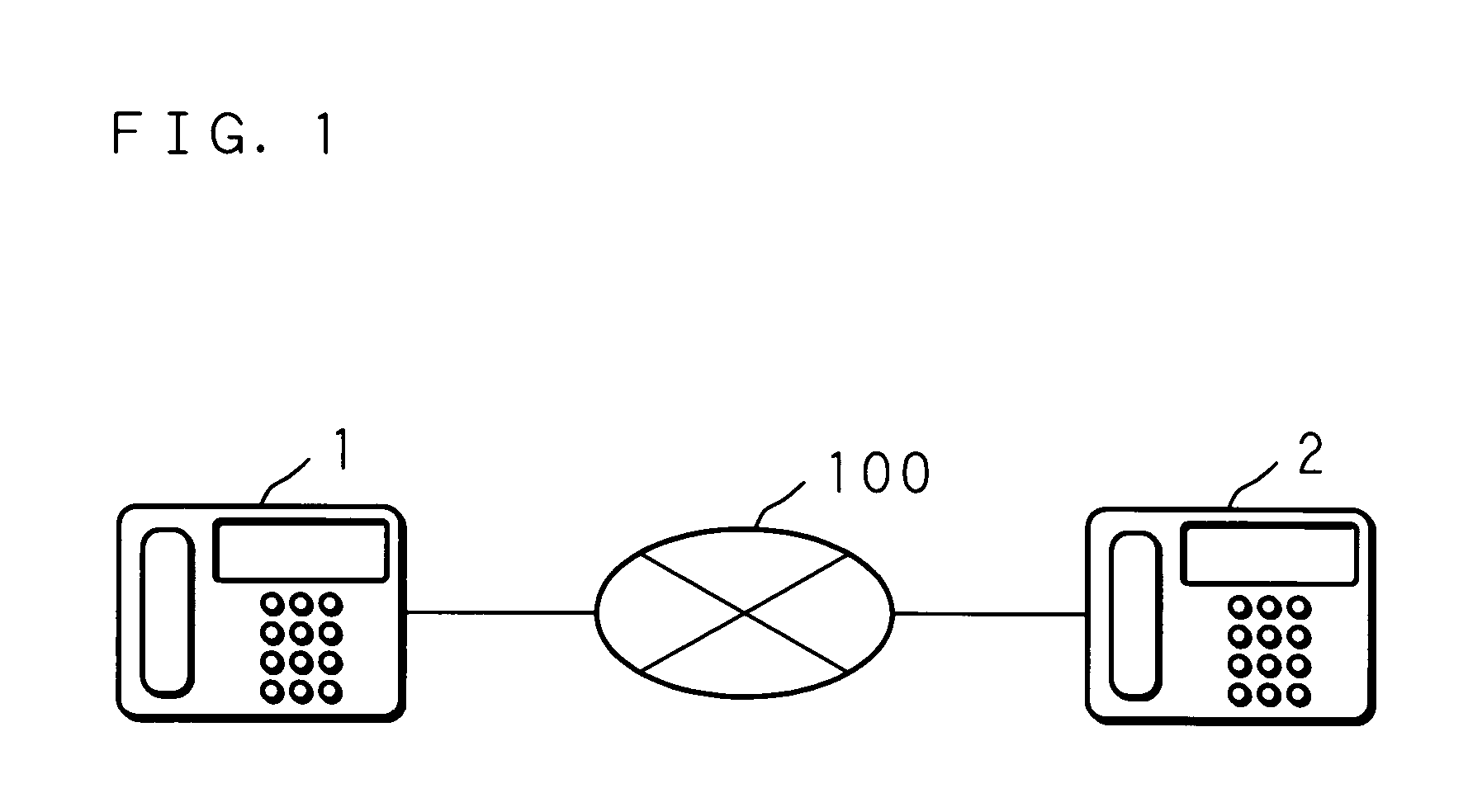
[0047]FIG. 1 is a schematic view showing conceptually an example of the configuration of a communication system using a data output apparatus of Embodiment 1 of the present invention.

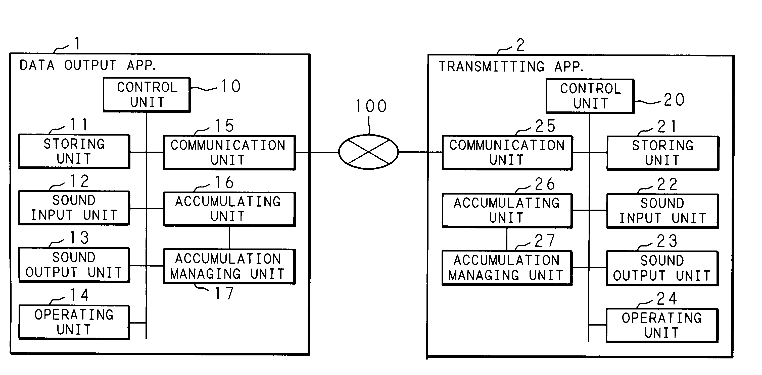
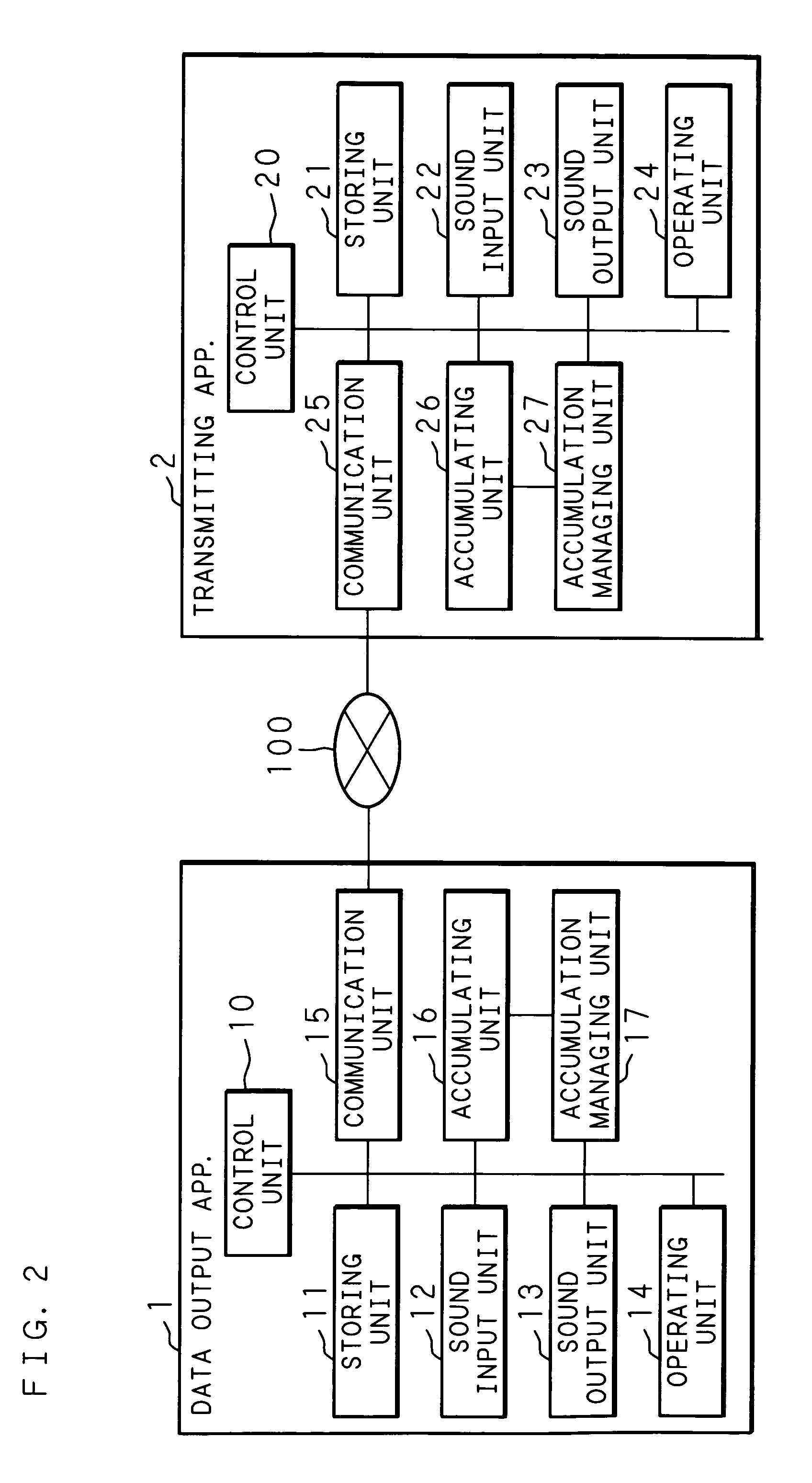
[0048]In FIG. 1, reference numeral 1 represents a data output apparatus of the present invention, and a computer for communication such as an IP telephony terminal apparatus is used. The data output apparatus 1 is connected to a communication network 100 such as a VoIP network composed of a relay apparatus such as an Internet router and communication lines, and performs packet communication with a transmitting apparatus 2 such as an IP telephony terminal apparatus. The transmitting apparatus 2 generates packets including sound data for outputting inputted sound, and transmits the generated packets to the data output apparatus 1 through the communication network 100. The data output apparatus 1 outputs sound based on the sound data included in the packets received from the transmitting apparatus 2. The p...

embodiment 2

[0094]According to Embodiment 2 of the present invention, in Embodiment 1 of the present invention described above, the additional duration for extending the check period is not fixed, and the additional duration for extending the check period is determined dynamically according to the occurrence of the non-accumulated state of sound data. However, since the configuration of a communication system using a data output apparatus of Embodiment 2 is basically the same as that of Embodiment 1, the explanation thereof will be omitted. In Embodiment 2, since the additional duration for extending the check period is not fixed, the check interval managing unit 173 does not need to store the additional duration for extending the check period as a parameter. However, the check interval managing unit 173 needs to store the time point at which the occurrence of constant delay was detected as described later.

[0095]The following description will explain the processes performed by the data output a...

embodiment 3

[0104]According to Embodiment 3 of the present invention, in Embodiment 2 of the present invention described above, when the non-accumulated state of sound data occurs a plurality of times within one check period, the additional duration for extending the check period is determined according to the state of occurrence. However, since the configuration of a communication system using a data output apparatus of Embodiment 3 is basically the same as that of Embodiment 1, the explanation thereof will be omitted. In Embodiment 3, the check interval managing unit 173 manages the time point at which the occurrence of constant delay was detected and the time point of the occurrence of the non-accumulated state as the additional duration calculation reference time points to be used as the bases for calculating the additional duration.

[0105]The following description will explain the processes performed by the data output apparatus 1 of Embodiment 3 of the present invention.

[0106]FIG. 12 is a ...


PUM


Abstract

A data output apparatus checks data accumulated state in the accumulating unit at a preset check interval, and changes at least one setting among an initial accumulation amount to be used as a basis for starting to output the data accumulated in the accumulating unit, an upper accumulation limit amount to be used as a basis for discarding accumulated data, and a check interval, according to a discarded state of the data based on check results. Therefore, in the data output apparatus such as an IP telephony terminal apparatus, it is possible to prevent sound interruption and limit a lowering of communication quality.

Description

CROSS-REFERENCE TO RELATED APPLICATION[0001]This non-provisional application claims priority under 35 U.S.C. §119 (a) on Patent Application No. 2005-51992 filed in Japan on Feb. 25, 2005, the entire contents of which are hereby incorporated by reference.BACKGROUND OF THE INVENTION[0002]1. Field of the Invention[0003]The present invention relates to a data output method for temporarily accumulating received data and performing output based on the accumulated data, a data output apparatus adopting such a data output method, and a computer program product for realizing such a data output apparatus. In particular, the present invention relates to a data output method, a data output apparatus, and a computer program product suitable for real-time communication such as VoIP and streaming distribution.[0004]2. Description of Related Art[0005]In recent years, there is an increasing use of applications that enable real-time communication such as VoIP (Voice over Internet Protocol), VoPN (Voi...

Claims


Application Information

Patent Timeline
Patent Type & Authority Patents(United States)
IPC IPC(8): G06F3/00G06F5/00H04L49/9023H04M1/00H04M11/00
CPCH04L47/10H04L47/22H04L47/283H04L47/32H04L65/80
Inventor HORIO, KENICHIOHNO, TAKASHIOKUYAMA, SATOSHI
Owner FUJITSU LTD
Features
  • R&D
  • Intellectual Property
  • Life Sciences
  • Materials
  • Tech Scout
  • Unparalleled Data Quality
  • Higher Quality Content
  • 60% Fewer Hallucinations
Learn More