Tooth system

a technology of tooth and adapter, which is applied in the field of tooth system, can solve the problems of wear of the tooth excavating part of the tooth, the replacement of the adapter is therefore much more cumbersome than the one before, and achieves the effect of better protection of the adapter against wear and better support of the tooth

Inactive Publication Date: 2010-04-06
IHC HOLLAND NV
View PDF7 Cites 13 Cited by
  • Summary
  • Abstract
  • Description
  • Claims
  • Application Information

AI Technical Summary

Benefits of technology

[0004]The object of the invention is therefore to provide a tooth system of the type described before, which provides for a better support of the tooth with respect to its adapter, as well as for a better protection of the adapter against wear. This object is achieved in that at least one pair of correspondingly shaped facing zones of the adapter and the tooth comprises a stepped configuration.
[0005]The advantages of the stepped configuration of the facing zones of the adapter and the tooth according to the invention are twofold. First of all, such stepped layout of the facing zones represents a stable support for the tooth with respect to the adapter. The stepped zones represent separate areas for supporting the tooth, suitable for withstanding forces and bending moments exerted on the tooth. Moreover, such separate areas offer the possibility to accommodate any imperfections in the facing surfaces without impairing the stability of the tooth, which imperfections may result from the manufacturing process of the components in question.
[0006]Furthermore, the stepped configuration enables an easy replacement of the tooth with respect to the adapter. In this connection, preferably the stepped configuration may define a wide cavity section and a narrow cavity section of the adapter, whereby the wide cavity section borders the front end of the adapter. Alternatively or additionally, the stepped configuration may define a thin adapter flange section and a thick adapter flange section, whereby the thin adapter flange section borders the front end of the adapter. In particular, such stepped configuration comprises several lands and recesses of the pair of facing zones, whereby each time a pair of a land of the one component, and a recess of the other component are facing each other. Preferably, the adapter has at least an adapter recess bordering the front and thereof and at least an adapter land at the end of the adapter recess opposite the front and, in which case the tooth has at least a tooth land opposite the adapter recess and at least a tooth recess opposite the adapter land.
[0007]The recesses may have a larger longitudinal dimension than the corresponding lands. In such a layout, the facing recesses will overlap each other over a certain extent, thus providing a gap in the area of the overlap. Such layout provides advantages as to the accommodation of imperfections as addressed before.
[0011]In a known way, the tooth comprises a front cover which is known per se. In the tooth system according to the invention, said front cover extends transversely with respect to the tooth web and faces the front end of the adapter. Preferably, the front cover of the tooth abuts the front end of the adapter so as to avoid clenching of the tooth with respect to the adapter which would prevent replacement of the tooth. In this connection, a further improvement of the tooth system according to the invention can be obtained in case the tooth head and the front cover are connected to each other, for instance at a sharp angle. The combined effect of the interconnected tooth head and front cover provides an advantageous shielding of the areas of the adapter which would otherwise be prone to the abrasive influences of the materials. Furthermore, the interconnected tooth head and front cover provide an additional stabilizing effect with respect to the correspondingly shaped adapter, the front of which is snugly surrounded by said combined tooth head and front cover.
[0013]For further improving the support of the tooth with respect to the adapter, the undercut cavity of the adapter may be tapered from a relatively wide front end to a relatively narrow back end, the tooth base having a corresponding taper. The front cover is at the relatively wide front end of the adapter and the locking element is at or near the relatively narrow back end of the adapter.

Problems solved by technology

These materials exert considerable forces on the teeth and also on the adapter, leading to wear of the tooth excavating part of the teeth, which therefore have to be replaced from time to time.
However, it appears that the adapters also may suffer from considerable wear.
This poses a problem in that said adapters in some cases are fixedly connected to e.g. the teeth bars of a draghead, such as by welding.
The replacement of adapters is therefore much more cumbersome than the replacement of the teeth, which indeed have expressly been carried out for easy replacement.
Worn out adapters however have the disadvantage that their function of firmly holding the teeth in place, is adversely influenced.
The teeth in question will no longer be supported in an adequate way, which leads to a certain play of the tooth with respect to its adapter.
These phenomena of play however further impair the proper functioning of the cutter head.

Method used


Image

  • Tooth system
  • Tooth system
  • Tooth system

Examples


Embodiment Construction

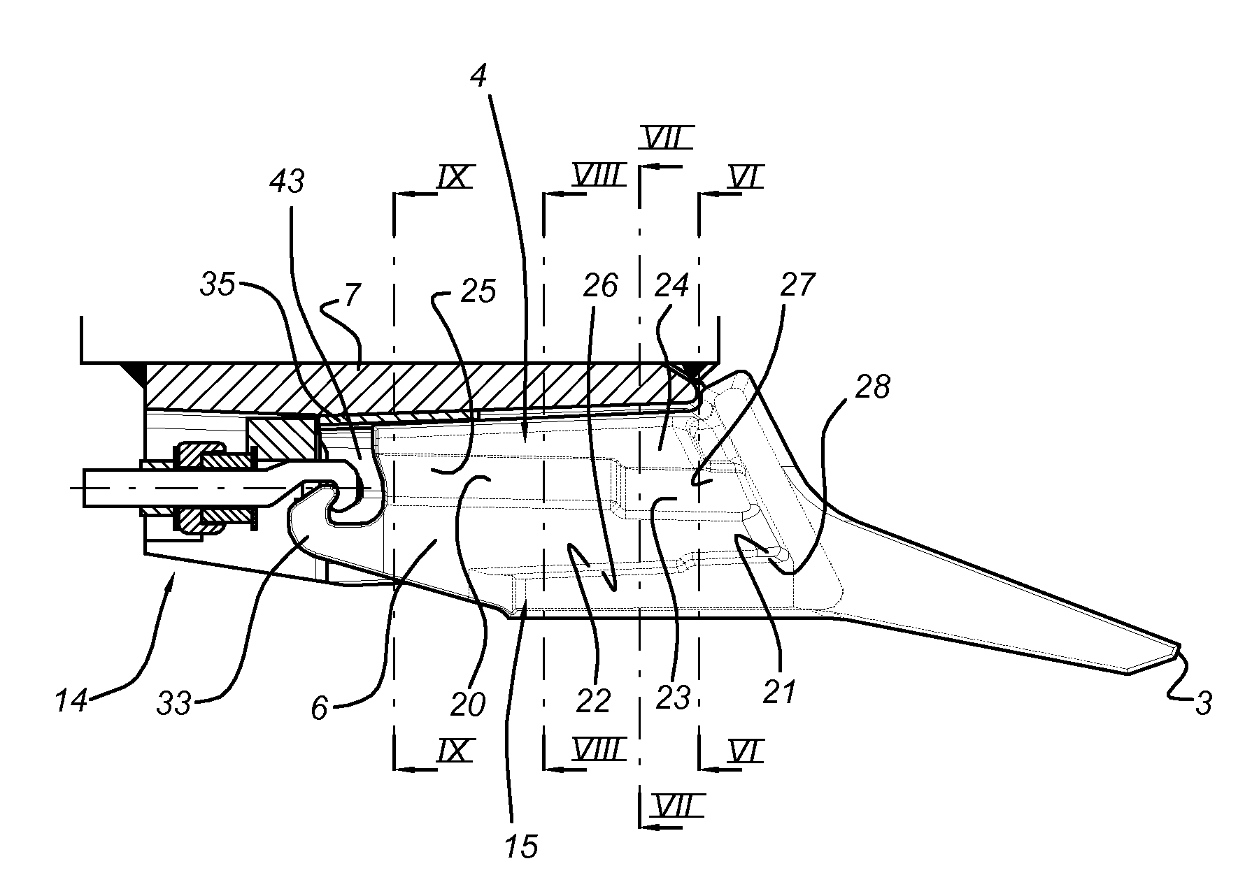
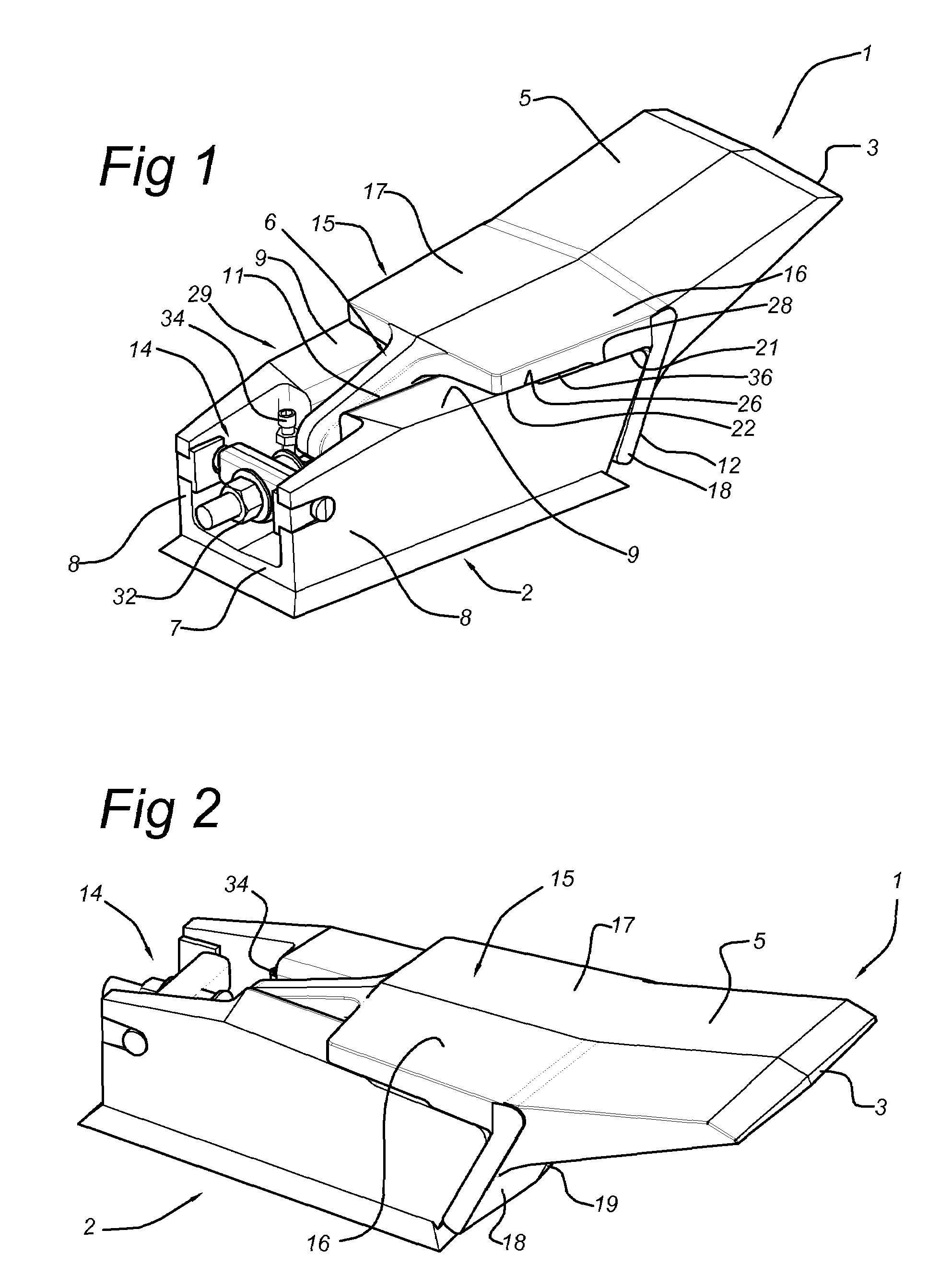
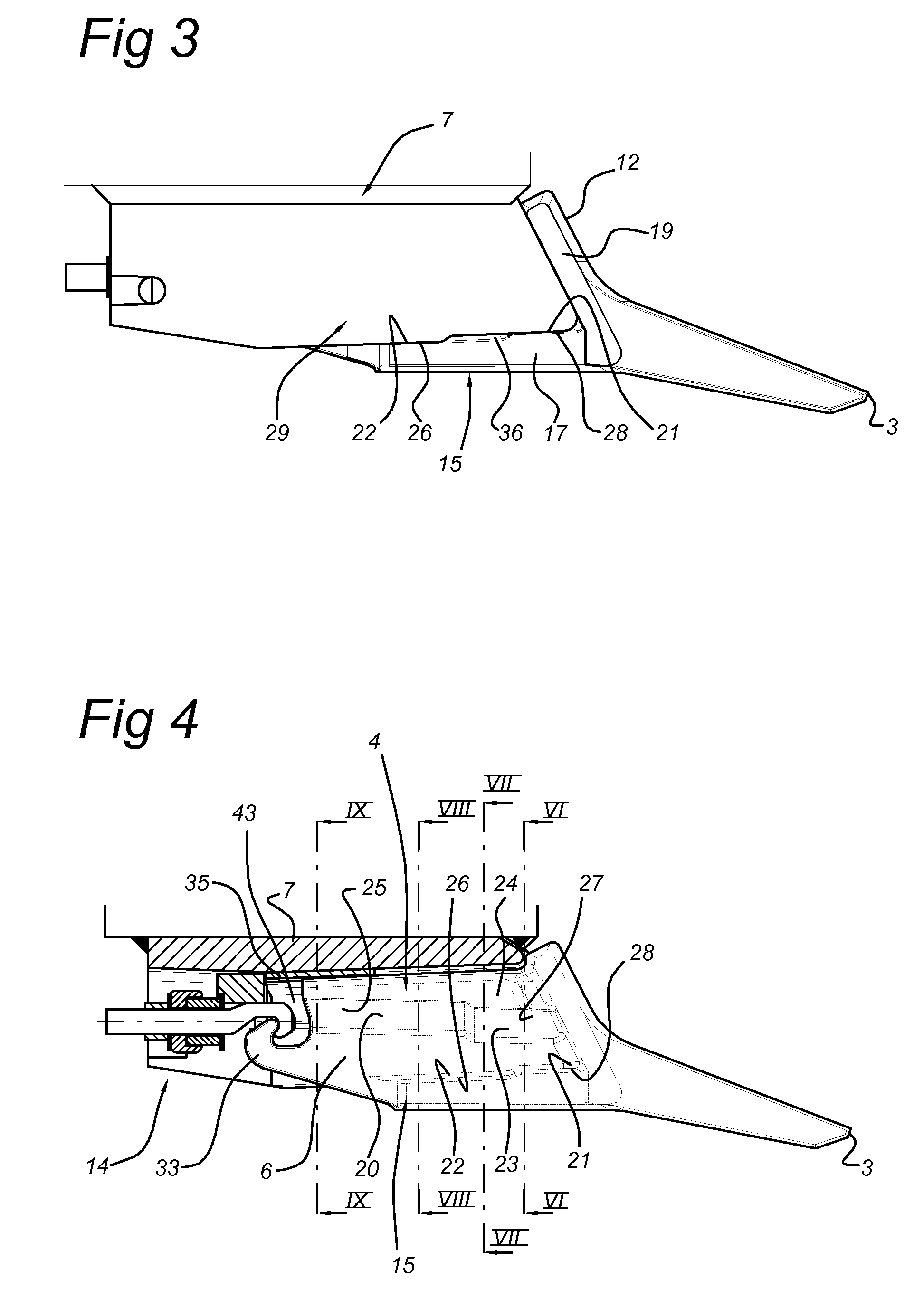
[0036]The tooth system according to the invention, as shown in the figures, comprises a tooth 1 connected to the adapter 2. Said tooth 1 comprises a tooth base 4, as shown in FIGS. 4, 10 and 11, as well as a tooth excavating element 5 with a cutting edge 3. Furthermore, the tooth comprises a tooth web 6 which extends between the base 4 and the tooth head 15. Said tooth head 15 is located opposite the tooth base 4. The adapter 2 comprises an adapter base 7 having two opposite upstanding walls 8 which support the adapter head 29. The adapter head 29 is provided with facing adapter flanges 9. Said adapter base 7, upstanding walls 8 and adapter head 29 with adapter flanges 9 define an undercut cavity 10 which by means of slit 11 opens out at the position of the adapter flanges 9.

[0037]As shown in FIGS. 1-5, the tooth base 4 of the tooth 1 has been slid into the undercut cavity 10 of the adapter 2. At the same time, the tooth web 6 of the tooth 1 has been accommodated in the slit 11 of t...


PUM


Abstract

A tooth system for use in an earthmoving device, includes a tooth and an adapter onto which the tooth is mounted in a detachable fashion, the tooth including a longitudinally extending tooth web, a longitudinally extending tooth base and a longitudinally extending tooth head at a distance from the tooth base, the tooth base and tooth head also extending transversely with respect to the web. The adapter includes an adapter base intended to be fixed onto an earthmoving device, such as onto the teeth bars of a draghead, and an adapter head, a longitudinally extending undercut cavity being defined between the adapter base and the adapter head, wherein the tooth base is slidably fitted within the undercut cavity and wherein the adapter head is slidably fitted between the tooth base and the tooth head for mounting or dismounting the tooth with respect; to the front end of the adapter.

Description

BACKGROUND OF THE INVENTION[0001]The invention is related to a tooth system for use in an earthmoving device, such as a dredging or mining device, comprising a tooth and an adapter onto which the tooth is mounted in a detachable fashion, said tooth comprising a longitudinally extending tooth web, a longitudinally extending tooth base and a longitudinally extending tooth head at a distance from the tooth base, said tooth base and tooth head also extending transversely with respect to the web, said adapter comprising an adapter base which is to be fixed onto an earthmoving device, such as onto the teeth bars of a draghead, and an adapter head, a longitudinally extending undercut cavity being defined between the adapter base and the adapter head, wherein the tooth base is slidably fitted within the undercut cavity and wherein the adapter head is slidably fitted between the tooth base and the tooth head for mounting or dismounting the tooth with respect to the front end of the adapter, ...

Claims


Application Information

Patent Timeline
Patent Type & Authority Patents(United States)
IPC IPC(8): E02F9/28
CPCE02F9/2858E02F9/2825E02F9/28
Inventor BREKEN, ROELOF
Owner IHC HOLLAND NV
Why Eureka
Try Eureka