Multiple fluid dispenser

a fluid dispenser and fluid technology, applied in liquid transfer devices, liquid handling, packaging goods types, etc., can solve the problems of dripping, slow and inaccurate volumetric dispensing, and inability to accurately dispense fluids, etc., to achieve efficient dripping and less fluid was

Inactive Publication Date: 2010-04-06
FLUID MANAGEMENT LLC
View PDF32 Cites 43 Cited by
  • Summary
  • Abstract
  • Description
  • Claims
  • Application Information

AI Technical Summary

Benefits of technology

[0021]In another refinement, the disclosed system comprises housing cabinetry designed in such a way that each module is detachably connected to the cabinetry so that each module may be easily exchanged or replaced. Further, the cabinetry is also preferably designed so that additional modules may be added easily.
[0030]In a different refinement, when a vertical hard-shell reservoir is utilized, such a reservoir may be designed so that an upper portion of the vertical reservoir has a square cross-section and a lower portion of the reservoir has a round cross-section. The upper square cross-section provides larger volumes when two reservoirs are supported next to each other and the lower round cross-section enables the reservoir to be more efficiently drained so that less fluid is wasted.

Problems solved by technology

However, as disclosed in the above patents, the software or algorithms used to accurately dispense fluids volumetrically using nutating pumps is complicated and may require frequent calibration.
Further, volumetric dispensing can be slow and inaccurate if a fluid drip is retained at the end of a nozzle or manifold instead of dropping down into the container reservoir or if some of the fluid is lost to splatter.
Dispensing one ingredient at a time is a slow process and when more than a few consumers are waiting to use a machine, they may be discouraged and wish to take their business elsewhere.
One way in which the precision of dispensing systems is compromised is “dripping.” Specifically, a “leftover” drip may be hanging from a nozzle that was intended to be added to a previous formulation and, with a new container in place under the nozzle, the drop of liquid intended for a previous formulation may be erroneously added to a new formulation.
Thus, the previous container may not receive the desired amount of the liquid ingredient and the next container may receive too much.
However, these designs often require one or more different motors to operate the wiper element and are limited to use on dispensing systems where the nozzles are separated or not bundled together in a manifold.
Use of a wiper or scraping function would not be practical in a multiple nozzle manifold design as the ingredients from the different nozzles will be co-mingled by the wiper or scraper which would then also contribute to the lack of precision of subsequently produced formulations.
Another problem associated with dispensing systems that make use of nozzles lies in the dispensing of relatively viscous liquids such as tints, colorants, base materials for cosmetic products, certain pharmaceutical ingredients or other fluid materials having relatively high viscosities.
While some mechanical wiping or scrapping devices are available, these devices are not practical for multiple nozzle manifold systems and the scraper or wiper element must be manually cleaned anyway.
To date, applicants are not aware of any attempts to provide any sort of nozzle or manifold closure or sealing element that would protect against drips as well as reducing the frequency in which the nozzle or manifolds must be cleaned.
Another problem associated with the machines described above, is the relative inflexibility of their design.
While some machines may dispense smaller amounts of materials such as tints or colorants from flexible bags and larger quantities of base material or solvent from rigid containers, no currently available machine is able to be easily adapted in the event the packaging for a raw material or an ingredient changes from a bag to a rigid container or vice versa.
In short, currently available systems are not easy to modify or adapt to different uses or for dispensing different materials.

Method used


Image

  • Multiple fluid dispenser
  • Multiple fluid dispenser
  • Multiple fluid dispenser

Examples


Embodiment Construction

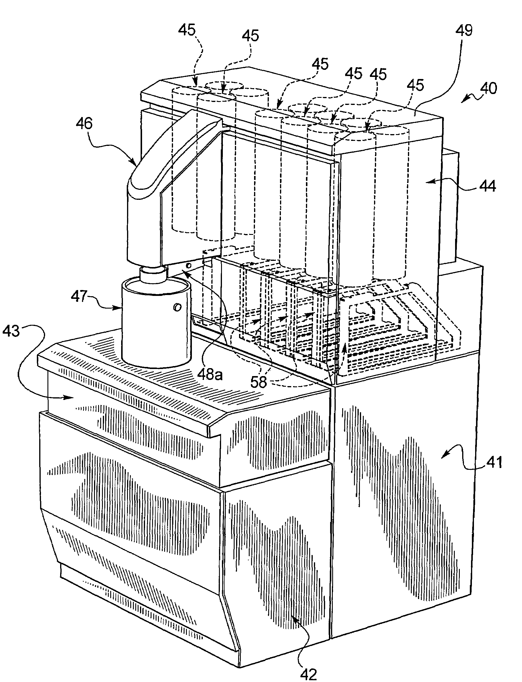
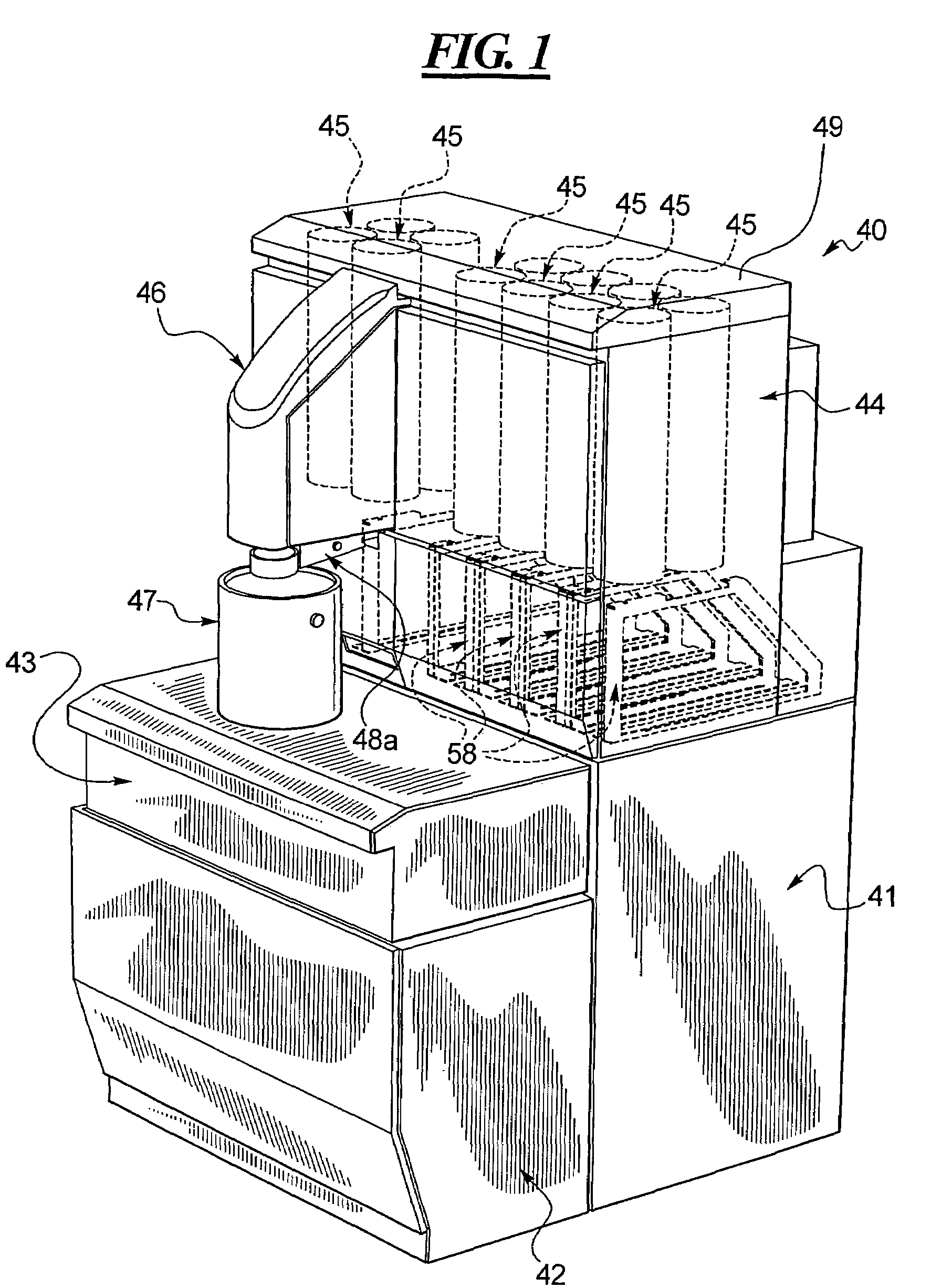
[0065]FIG. 1 discloses a dispensing apparatus 40 which includes a lower base portion 41 connected to a front cabinet 42 which, in turn, is disposed beneath in support a middle cabinet shown at 43. The middle cabinet 43 may also include a scale or weighing function (not shown). Any one of the cabinets 41 through 43 may house a controller and other electronic equipment (not shown). The cabinet 41 supports an upper cabinet 44 which, in turn, houses a plurality of modules which are represented by pairs of canisters shown generally at 45. In the examples shown in FIG. 1, six modules that each dispense two different fluids are shown for a total dispending of 12 different fluids. FIG. 1 also illustrates a manifold module 46 which will be described below. The sequential or, preferably simultaneous dispensing of one or more fluids from the 12 difference fluids provided in FIG. 1 is made through the manifold module 46 and down into the container 47. A manifold closure system is shown at 48a. ...


PUM

PropertyMeasurementUnit
flexibleaaaaaaaaaa
weightaaaaaaaaaa
sizeaaaaaaaaaa

Abstract

An improved multi fluid dispenser for simultaneous dispensing of a plurality of fluids shown and described. The dispenser includes a controller that is linked to a coordinator board. The controller has a memory with a plurality of recipes stored in the memory. A coordinator board is linked to a first module. The first module may include one or two pumps, each connected to a fluid reservoir. The module is then linked in series to a plurality of other modules as well as a manifold module. Each module includes a module board for controlling the pump or pumps of that module. The controller, coordinator board and module boards are all programmed for the simultaneous or sequential pumping of multiple fluids from the reservoirs through outlet nozzles of the manifold in accordance with a recipe selected by the user and retrieved from the memory of the controller.

Description

BACKGROUND[0001]1. Technical Field[0002]An apparatus is disclosed for dispensing a plurality of fluids according to one of the plurality of formulas stored in a controller. The controller is linked to a coordinating board which, in turn, is linked in series to a plurality of pump modules and a manifold module. Each pump module includes its own module board which controls the operation of two pumps associated with that module. The modules, which include the module board, two pumps and two reservoirs as well as motors for driving the pumps, are all mounted on a module frame which is detachably connected to the system so that the modules may be easily changed or replaced. Further, the manifold module may also be easily replaced. The manifold module also includes a motorized closure system.[0003]2. Description of the Related Art[0004]Systems for dispensing a plurality of different fluids into a container have been known and used for many years. For example, systems for dispensing paint ...

Claims


Application Information

Patent Timeline
Patent Type & Authority Patents(United States)
IPC IPC(8): B65B3/12B65B3/26B67C3/02
CPCB01F13/1066B44D3/08B01F13/1055B01F7/00133B01F7/00141B01F7/00291B01F7/16B67D2001/0814B01F15/00123B05B1/28B01F27/0723B01F27/0724B01F27/1125B01F27/80B01F33/846B01F33/84B01F35/20
Inventor MILLER, WILLIAM A.HOGAN, TIMKHOO, CHRISTOPHERHANAWALT, RYANLEIDER, MARTYCLEVELAND, JAMES R.OBRECHT, ANTON
Owner FLUID MANAGEMENT LLC
Why Eureka
Try Eureka