Display mounting system and method

a technology for mounting systems and displays, applied in washstands, light support devices, scaffold accessories, etc., can solve the problems of not being able to mount a variety of displays having different sizes and weights, and achieve the effect of smooth movement, smooth movement, and easy adjustment of til

Active Publication Date: 2010-04-06
ERGOTRON
View PDF16 Cites 31 Cited by
  • Summary
  • Abstract
  • Description
  • Claims
  • Application Information

AI Technical Summary

Benefits of technology

[0004]Embodiments of the invention include mounts for mounting displays to a surface. Such mounts provide for the tilting of the display relative to the surface in a smooth manner with a minimum of moving parts. In some embodiments, the mount includes at least one surface sized and shaped to create cooperate reaction forces to counteract the moment created by the changing center of gravity location of the device panel to continuously immobilize the device panel within the range of angles allowed by the mount. Such a mount allows a user to easily adjust the tilt of even relatively large displays without locks, levers, or pins.

Problems solved by technology

Typically, these displays are mounted on such surfaces with a fixed mount that does not provide for adjustment of the position of the display.
That is, they are not able to mount a variety of displays having different sizes and weights.

Method used


Image

  • Display mounting system and method
  • Display mounting system and method
  • Display mounting system and method

Examples


Embodiment Construction

[0036]In the following detailed description, reference is made to the accompanying drawings which form a part hereof, and in which is shown by way of illustration specific embodiments in which the invention may be practiced. These embodiments are described in sufficient detail to enable those skilled in the art to practice the invention, and it is to be understood that other embodiments may be utilized and that structural changes may be made without departing from the scope of the present invention. Therefore, the following detailed description is not to be taken in a limiting sense, and the scope of the present invention is defined by the appended claims and their equivalents.

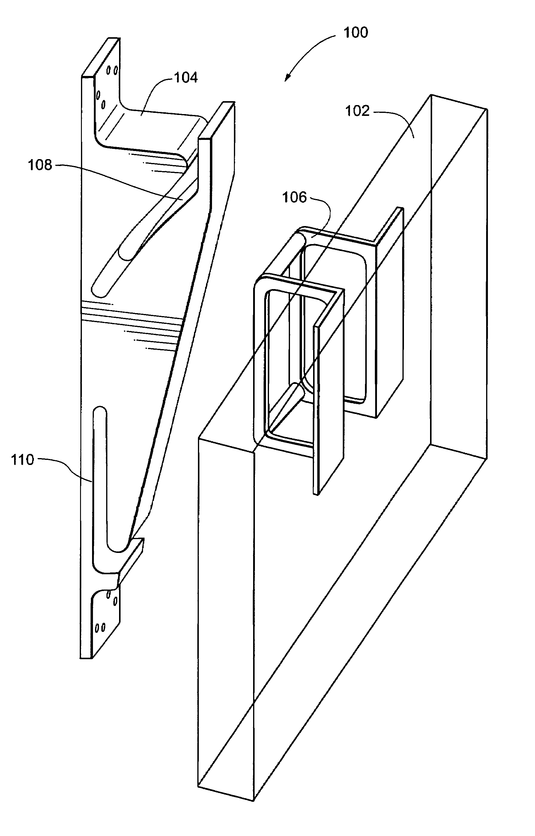
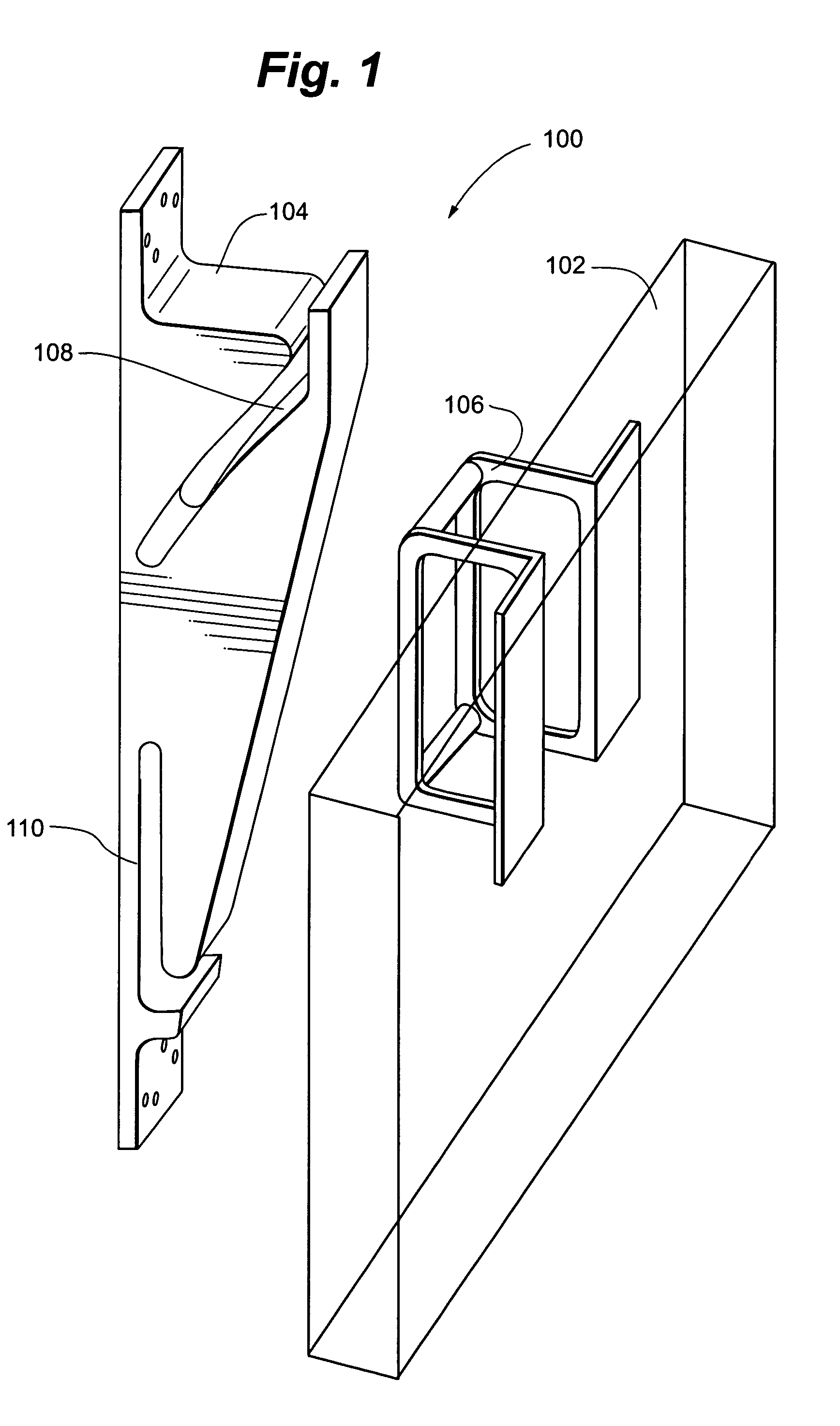
[0037]FIG. 1 shows an exploded perspective view of one example of a mounting system 100. The mounting system 100 operates to moveably couple an object, such as a display screen 102 to a surface (i.e., a wall, ceiling, columnar member or the like). The display screen 102 includes, but is not limited to, a plasm...


PUM


Abstract

A mounting system includes a first surface and a second surface. A device panel can include at least first and second engaging members. The first and second surfaces are sized and shaped to engage the first and second engaging members respectively, and the first and second engaging members move along the first and second surfaces. The first and second surfaces are sized and shaped so the reaction forces between the first and second engaging members and the mounting panel cooperate to counteract the moment created by the center of gravity of the device panel to continuously immobilize the device panel at the plurality of angles relative to the support surface.

Description

RELATED APPLICATIONS[0001]This application claims priority to U.S. Provisional Patent Application Ser. No. 60 / 620,084, filed Oct. 19, 2004, and titled “Slotted Display Screen Mount and Method,” the contents of which are hereby incorporated by reference.TECHNICAL FIELD[0002]The invention relates to devices and methods for moveably supporting equipment including, but not limited to, flat panel display screens such as plasma screens, liquid crystal display screens, etc.BACKGROUND[0003]Display screens, such as flat panel displays, are commonly mounted on surfaces such as walls, ceilings, inclined surfaces, poles and / or carts. Typically, these displays are mounted on such surfaces with a fixed mount that does not provide for adjustment of the position of the display. In mounts that have provided for the adjustment of the position of the display, the mounts fend to have many moving parts, such as springs and locking systems. In addition, such mounts tend to be specifically adapted for a s...

Claims


Application Information

Patent Timeline
Patent Type & Authority Patents(United States)
IPC IPC(8): E04G3/00
CPCF16M11/10F16M13/02F16M13/027Y10S248/917Y10S248/919Y10S248/921F16M2200/022
Inventor ASAMARAI, SAEBFLUHRER, ROBERT W.LINDBLAD, SHAUN C.ALZEBDEH, KHALID
Owner ERGOTRON
Why Eureka
Try Eureka