Method and apparatus for making electrolyzed water

a technology of electrolysis cell and end cap, which is applied in the direction of liquid/fluent solid measurement, separation process, filtration separation, etc., can solve the problems of many existing cells starting to leakage and high breakage rate, and achieve the effect of boosting the immune system

Active Publication Date: 2010-04-06
CLARTECH HLDG
View PDF8 Cites 35 Cited by
  • Summary
  • Abstract
  • Description
  • Claims
  • Application Information

AI Technical Summary

Benefits of technology

[0011]With the insulating end caps of the invention, the assembly of the cell can be greatly simplified, avoiding damage to components and allowing easier visual inspection at all stages of construction. Craft skills are not necessary, and sealants can more easily be used, avoiding the need for mechanical gasket or O-ring seals. The use of such non-toxic sealants helps to avoid leakages and imparts increased pressure resistance.
[0043]A spiral feed of electrolyte into the anode and cathode chambers leads to turbulization of the electrolytes in the chambers of the electrical cell, prolongs influence of electrolysis over elementary amounts of the processed water solutions, simplifies removal of gaseous and liquid products of electrolysis and reduces possible formation of gas-filled zones in the upper points of electrode chambers.

Problems solved by technology

Cells of this type function quite well, but a problem arises in their construction.
A high degree of craft skill is required to assemble them, and in particular to assemble the cell components in the end bushes, and there is a high breakage rate.
Many existing cells start leaking over a period of time as component parts are mechanically sealed with gaskets.
During the lifetime of a cell, component parts become brittle, shrink or expand, causing leakages.

Method used


Image

  • Method and apparatus for making electrolyzed water
  • Method and apparatus for making electrolyzed water
  • Method and apparatus for making electrolyzed water

Examples


Embodiment Construction

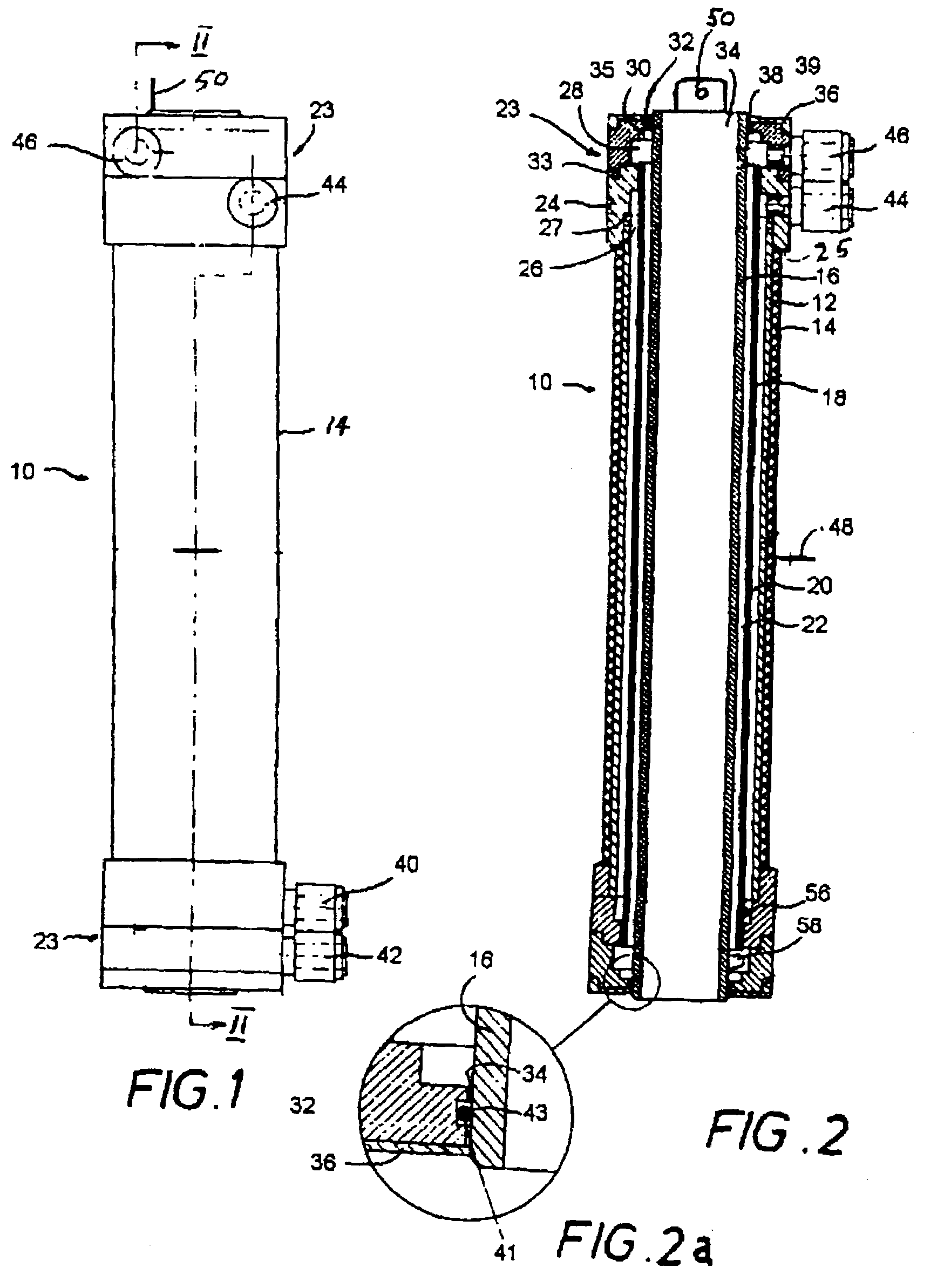
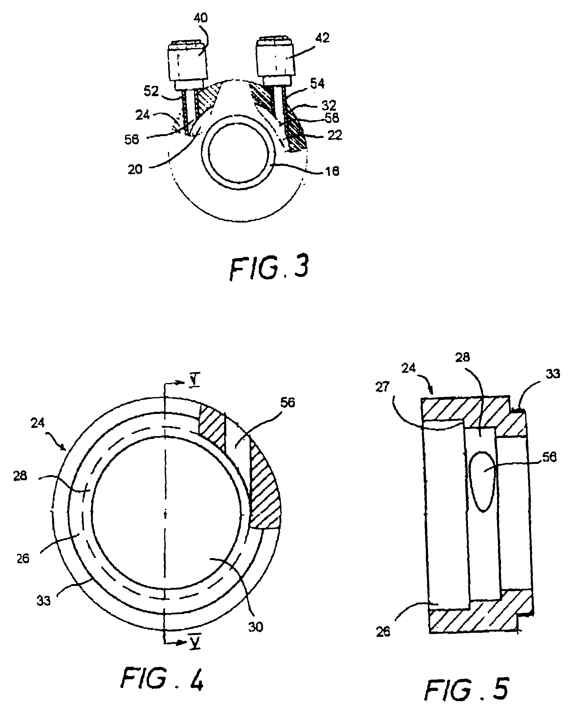
[0056]Referring first to FIGS. 1 and 2, a cylindrical electrolysis cell generally indicated by 10 comprises an outer cylindrical anode 12 enclosed on its outer surface by a cylindrical protective and insulating sleeve 14. This electrode is preferably made of titanium, coated on its inner surface with a transition metal oxide coating as described above. An inner cylindrical cathode 16, also preferably made of titanium and with a transition metal oxide coating on its outer surface, is arranged co-axially within the cylindrical anode, and a cylindrical ion-permeable membrane 18 is arranged co-axially between the electrodes in such a way as to define a space 20 between the anode and the membrane, which in use acts as an anolyte compartment, and a space 22 between the membrane and the cathode, which in use becomes the catholyte compartment.

[0057]The ion-permeable membrane 18 is preferably a ceramic membrane, and is suitably made from allumina.

[0058]An insulating end cap 23 is provided at...


PUM

PropertyMeasurementUnit
mean particle sizeaaaaaaaaaa
thicknessaaaaaaaaaa

Abstract

An insulating end cap for a cylindrical electrolysis cell the type comprising at least two tubular electrodes with a cylindrical membrane arranged co-axially between them, comprises a first annular section with first and second axial ends, having at its first axial end a circular seating or one end of an outer cylindrical electrode and at its second end a circular aperture, of smaller diameter than the circular seating and co-axial therewith, to accommodate one end of the membrane. A second annular section of the end cap is detachably secured to the first and has a central circular aperture of smaller diameter than the central aperture of the first section and co-axial therewith, to accommodate one end of the inner cylindrical electrode. The two part construction of the end cap facilitates the assembly of the cell, and reduces the likelihood of breakage of the fragile ceramic membrane.

Description

BACKGROUND OF THE INVENTION[0001]1. Field of the Invention[0002]This invention relates to an insulating end cap construction for a cylindrical electrolysis cell of the type comprising at least two tubular electrodes arranged coaxially, one within the other, with a cylindrical membrane arranged coaxially between them.[0003]2. Description of the Prior Art[0004]Cells of the type to which the invention relates can be used for example for sanitising water through electrolysis for drinking purposes, or electrolysing brine solutions to make a powerful biocide. Many types of electrochemical activation and electrolysis cells exist for this purpose, and generally comprise two concentric cylindrical electrodes, one of which acts as a cathode and the other as an anode, an ion-permeable membrane being located coaxially between them to separate the space between the electrodes into anode and cathode compartments. An electrolyte such as brine is passed through the anode and cathode compartments, s...

Claims


Application Information

Patent Timeline
Patent Type & Authority Patents(United States)
IPC IPC(8): C02F1/00C02F1/28C02F1/461C02F1/467C02F1/48C25B9/19C25B9/23
CPCC02F1/46104C25B9/08C25B9/00C25B9/02C02F1/283C02F1/46109C02F1/4674C02F1/48C02F2001/46138C02F2201/46115C02F2201/46145C02F2209/04C02F2209/06C02F2201/003C25B9/63C25B9/19
Inventor DALY, JAMESVAN SCHAIK, MICHEL
Owner CLARTECH HLDG
Why Eureka
Try Eureka