
Method and apparatus to synchronize audio and video

a technology of audio and video, applied in the direction of differential synchronization source locking, selective content distribution, television systems, etc., can solve the problems of user still experiences audio/video timing difference errors and lip synchronization errors, and various delays

Inactive Publication Date: 2010-04-06
SAMSUNG ELECTRONICS CO LTD
View PDF14 Cites 42 Cited by
  • Summary
  • Abstract
  • Description
  • Claims
  • Application Information

AI Technical Summary

Benefits of technology

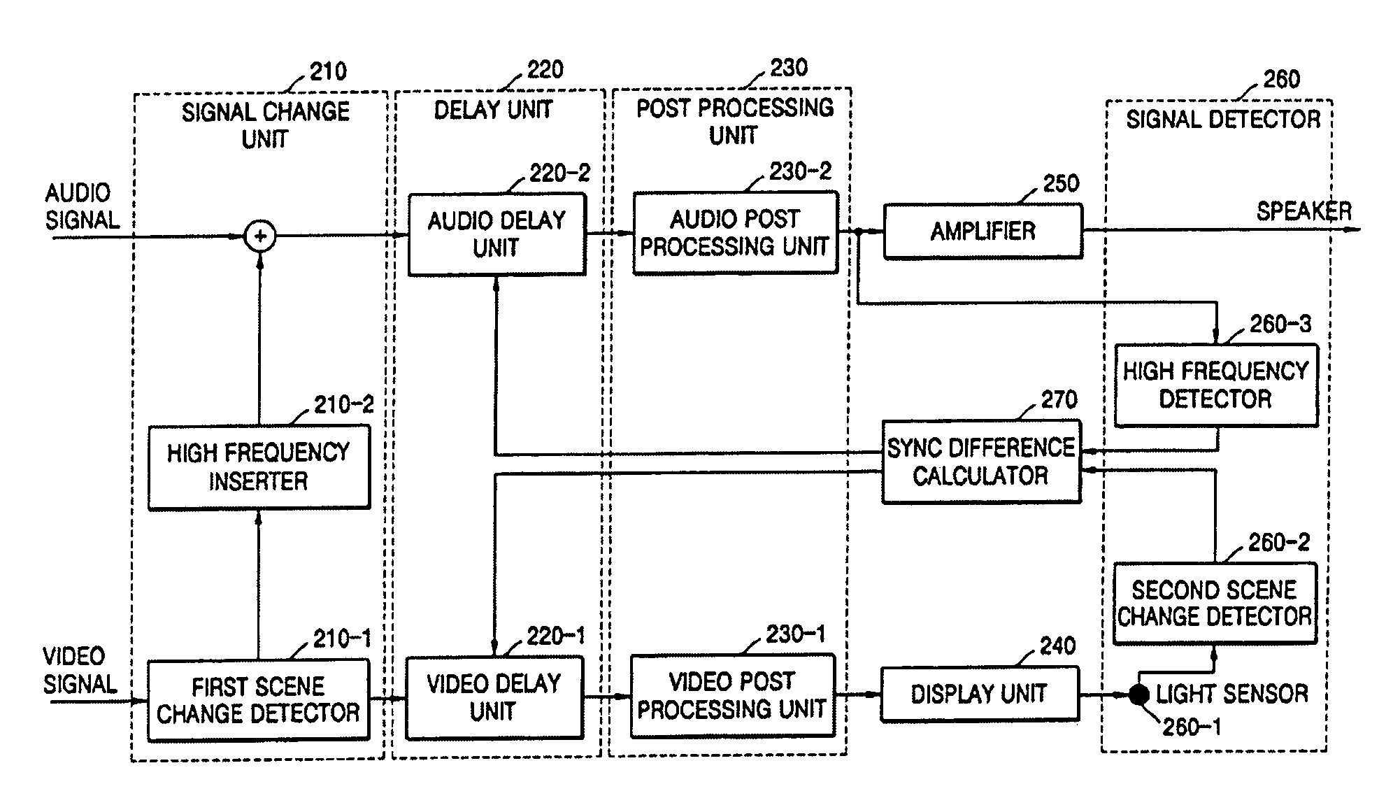
The present invention provides an audio and video synchronization apparatus and method that automatically synchronizes audio and video signals without needing to measure them separately. This is done by detecting scene changes in the video signal and inserting a high frequency component into the audio signal to indicate a scene change. The apparatus calculates the time difference between when the scene change is detected in the video and when the high frequency component is detected in the audio signal, and controls the buffering of the audio and video signals accordingly. This allows for seamless synchronization of audio and video without the need for manual adjustment.

Problems solved by technology

However, even though an audio signal and a video signal decoded to suit a TV or a storage medium are synchronized, a user still experiences audio / video timing difference errors and lip synchronization errors since various delays in the audio signal and the video signal can cause significant lip synchronization problems.
Processing operations performed on the audio and video signals after the audio and video signals have been decoded and synchronized (i.e., post processing) can cause the various delays.
The delays added in audio and video signal paths may cause the audio signal and the video signal to be unsynchronized.
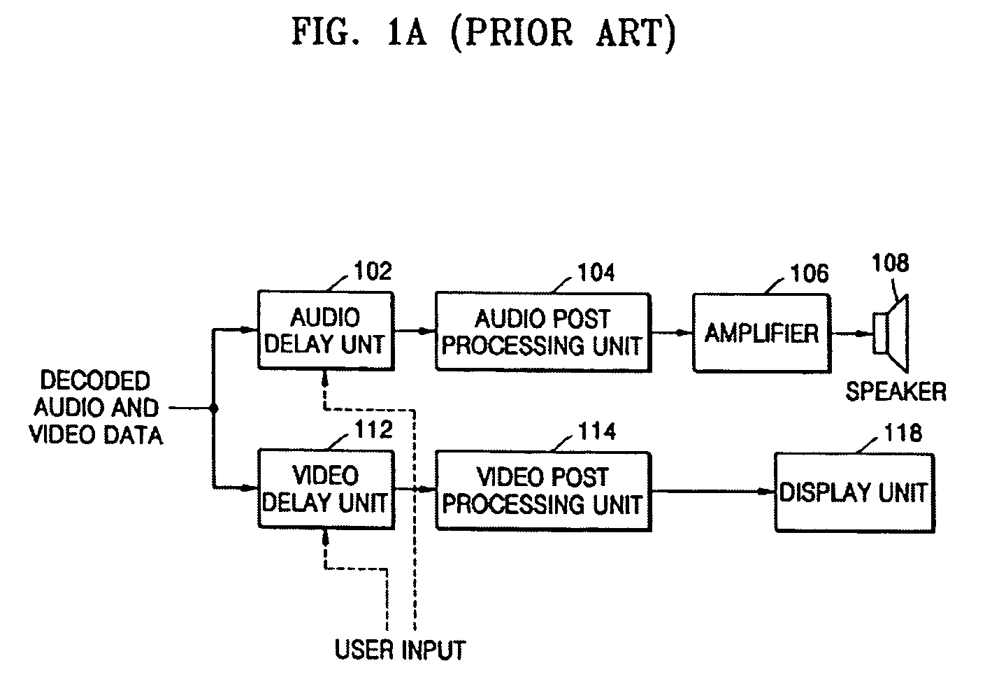
However, the first conventional audio and video synchronizing apparatus has a disadvantage in that a user is required to manually input audio signal delay parameters in order to resynchronize the audio signal and the video signal.
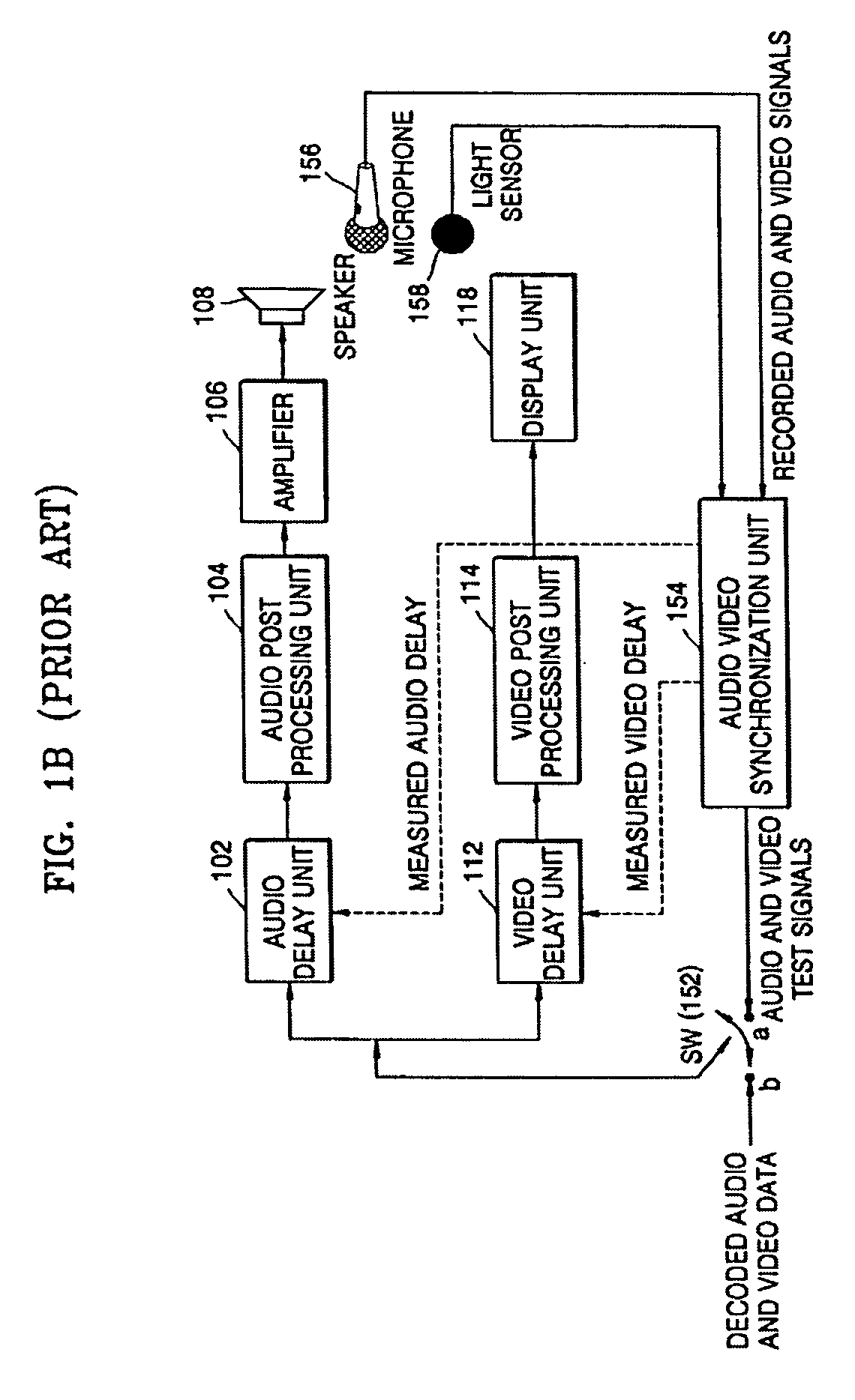
Additionally, the second conventional audio and video synchronizing apparatus has a disadvantage in that a separate measuring operation is required.

Method used


Image

  • Method and apparatus to synchronize audio and video
  • Method and apparatus to synchronize audio and video
  • Method and apparatus to synchronize audio and video

Examples


Embodiment Construction

[0029]Reference will now be made in detail to the embodiments of the present general inventive concept, examples of which are illustrated in the accompanying drawings, wherein like reference numerals refer to the like elements throughout. The embodiments are described below in order to explain the present general inventive concept while referring to the figures.

[0030]FIG. 2 is a block diagram illustrating an audio and video synchronizing apparatus according to an embodiment of the present general inventive concept. Referring to FIG. 2, the audio and video synchronizing apparatus includes a signal change unit 210, a delay unit 220, a post processing unit 230, a display unit 240, an amplifier 250, a signal detector 260, and a sync difference calculator 270.

[0031]The signal change unit 210 includes a first scene change detector 210-1 and a high frequency inserter 210-2.

[0032]The first scene change detector 210-1 calculates a luminance level difference between frames of a video signal a...


PUM


Abstract

A method and an apparatus to synchronize an audio signal and a video signal. The method includes: displaying video on a screen that corresponds to an audio signal including a high frequency component having a predetermined pattern inserted therein to indicate when a scene change occurs in a video signal, detecting a scene change in the displayed video and detecting the high frequency component having the predetermined pattern in the audio signal, calculating a time difference between a time when the scene change is detected in the displayed video and a time when the high frequency component having the predetermined pattern is detected in the audio signal, and controlling delay times of the audio signal and the video signal according to the calculated time difference. Accordingly, the audio signal and the video signal can be automatically synchronized without performing a separate measuring operation.

Description

CROSS-REFERENCE TO RELATED APPLICATIONS[0001]This application claims priority from Korean Patent Application No. 2004-81358, filed on Oct. 12, 2004, in the Korean Intellectual Property Office, the disclosure of which is incorporated herein in its entirety by reference.BACKGROUND OF THE INVENTION[0002]1. Field of the Invention[0003]The present general inventive concept relates to a method and an apparatus to synchronize an audio signal and a video signal, and more particularly, to a method and an apparatus to synchronize an audio signal and a video signal in multimedia.[0004]2. Description of the Related Art[0005]Since common multimedia, such as VCDs and DVDs, and common multimedia file formats, such as AVI, store audio and video synchronization information, an audio stream and a video stream are synchronized after decoding. However, even though an audio signal and a video signal decoded to suit a TV or a storage medium are synchronized, a user still experiences audio / video timing di...

Claims


Application Information

Patent Timeline
Patent Type & Authority Patents(United States)
IPC IPC(8): H04N9/475H04N5/44
CPCG11B27/10G11B27/28H04N5/04H04N21/44008H04N21/233H04N21/23418H04N21/422H04N21/4305H04N21/4307H04N7/08H04N5/147H04N5/4401H04N5/602H04N21/426H04N21/43072
Inventor ARORA, MANISHLARCYCGUIN, SERGUEI
Owner SAMSUNG ELECTRONICS CO LTD
Learn More