DLL with false lock protector

a false lock and protector technology, applied in the direction of electrical equipment, automatic control, pulse, etc., can solve the problems of inability to prevent locking to a higher delay time of nt, inaccurate delay times, and conventional methods also have drawbacks

Inactive Publication Date: 2005-01-18
QUALCOMM INC
View PDF6 Cites 43 Cited by
  • Summary
  • Abstract
  • Description
  • Claims
  • Application Information

AI Technical Summary

Problems solved by technology

A problem with conventional phase detectors is that because the delay time of delay cells used in an analog delay line may vary greatly depending on the control voltage, the delay time may be less than 0.5T or larger than 1.5T, resulting in inaccurate delay times.
Conventional DLLs can prevent the delay line from being locked to a delay time of 2T, but cannot prevent locking to a higher delay time of nT (where n=3, 4, . . . ).
However, conventional methods also have a drawback, requiring an additional DLL when the delay time of one delay cell is greater than 1.5T.

Method used


Image

  • DLL with false lock protector
  • DLL with false lock protector
  • DLL with false lock protector

Examples


Embodiment Construction

It should be appreciated that the present invention can be implemented in numerous ways, including as a process, an apparatus, a system, or a computer readable medium such as a computer readable storage medium or a computer network wherein program instructions are sent over optical or electronic communication links. It should be noted that the order of the steps of disclosed processes may be altered within the scope of the invention.

A detailed description of one or more preferred embodiments of the invention is provided below along with accompanying figures that illustrate by way of example the principles of the invention. While the invention is described in connection with such embodiments, it should be understood that the invention is not limited to any embodiment. On the contrary, the scope of the invention is limited only by the appended claims and the invention encompasses numerous alternatives, modifications and equivalents. For the purpose of example, numerous specific detail...


PUM


Abstract

A system and method are disclosed for providing a DLL with false lock protector to avoid false lock and ensure accurate lock. The false lock protector operates when the initial delay time between signals from an input reference clock and an output clock exceeds the lock range during operation of the DLL. The DLL with false lock protector includes a reference clock, a delay line composed of several delay cells connected in series, a phase detector, comparator for comparing phases of signals from the reference and output clocks, a determinator and a controller for controlling the delay of the delay line.

Description

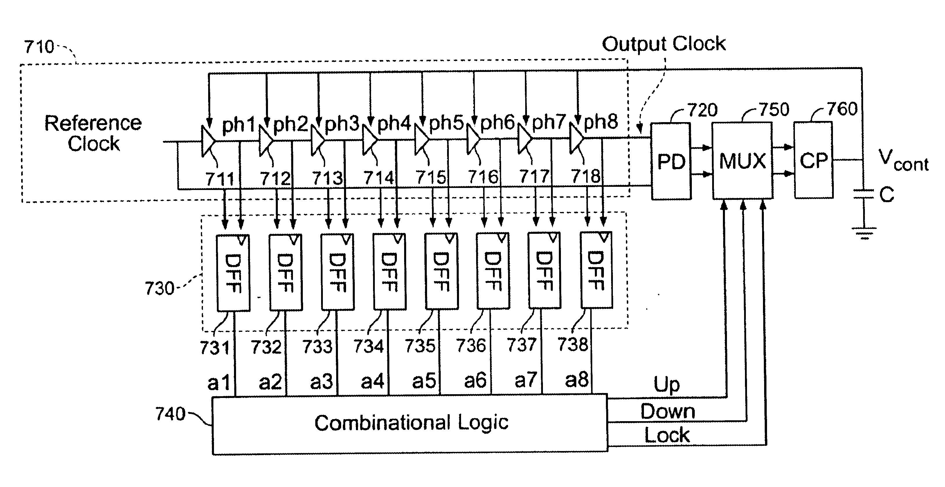
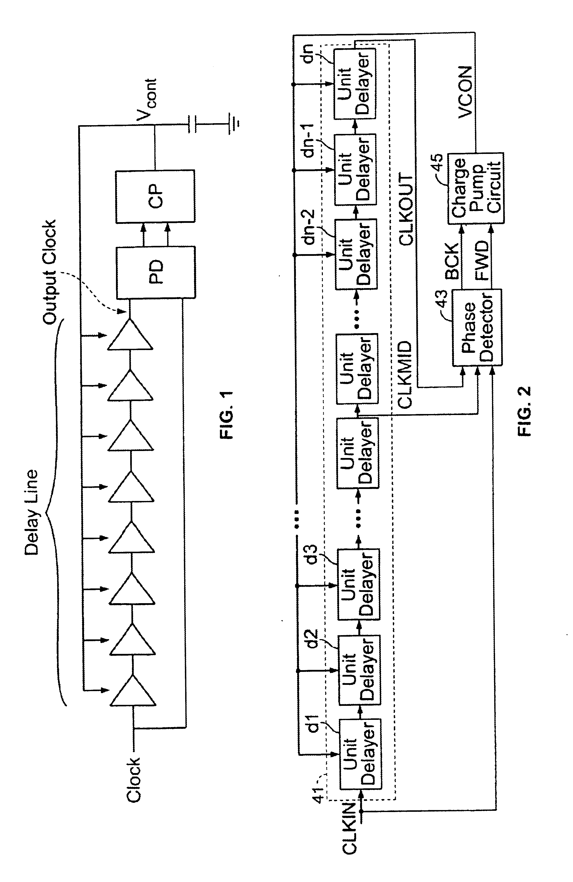
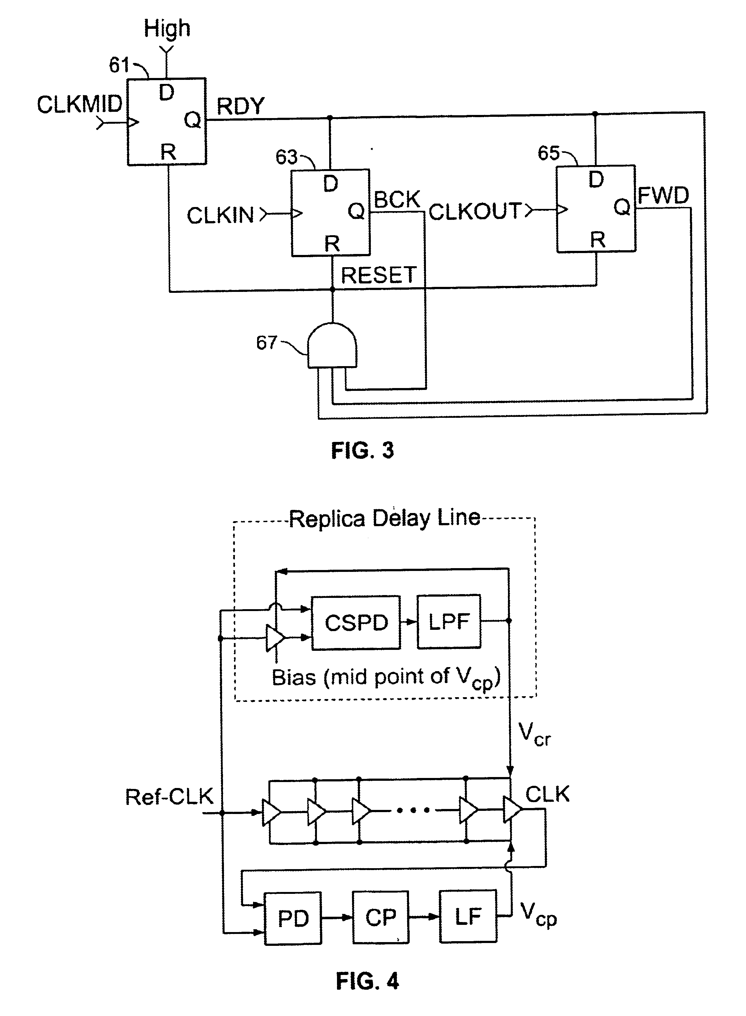
FIELD OF THE INVENTIONThe present invention relates generally to a delay locked loop. More specifically, a technique for false lock protection is disclosed.BACKGROUND OF THE INVENTIONIn general, a delay locked loop (“DLL”) is a circuit that compares phases of the rising edges of signals from an input reference clock and an output clock through a phase detector (“PD”). FIG. 1 illustrates an embodiment of a conventional locked loop circuit for the general purpose described above. On the basis of the result of the comparison of the rising edges of the input reference clock and the output clock through a PD, a DLL implements control using a charge pump (“CP”) and a capacitor (C), configured as shown. The delay time of the delay line includes several delay cells to match the rising edges of the input reference and output clocks.When a DLL is used in a system that requires an accurate delay time, it is important that the delay time of the delay line be the same as a period T. If the actua...

Claims


Application Information

Patent Timeline
Patent Type & Authority Patents(United States)
IPC IPC(8): H03L7/089H03L7/081H03L7/08H03L7/00
CPCH03L7/0812H03L7/0891H03L2207/14H03L7/0816H03L7/00
Inventor BYUN, SANG JINKIM, BEOMSUPPARK, CHAN-HONG
Owner QUALCOMM INC
Why Eureka
Try Eureka