Signal processing system and method, signal processing apparatus and method, recording medium, and program

a signal processing and signal processing technology, applied in the field of signal processing systems and methods, signal processing apparatuses and methods, recording media, programs, etc., can solve the problems of reducing operability, affecting the operation of the signal processing board, so as to facilitate the change of the signal processing function

Inactive Publication Date: 2010-04-06
SONY CORP
View PDF19 Cites 6 Cited by
  • Summary
  • Abstract
  • Description
  • Claims
  • Application Information

AI Technical Summary

Benefits of technology

[0009]Accordingly, in view of the above background, it is an object of the present invention to easily select one of a plurality of signal processing functions provided for a signal processing apparatus and to utilize the selected function.
[0052]According to the above-described signal processing systems, apparatuses, methods, recording media, and programs, it is possible to implement a system that can change a signal processing function. In this system, a plurality of signal processing functions of the signal processing apparatus can be easily selected and utilized.
[0104]According to the above-described signal processing systems, apparatuses, methods, recording media, and programs, it is possible to implement a system that can easily change a signal processing function. In this system, even if information for changing the signal processing function is updated, the updated information can be provided while maintaining security.

Problems solved by technology

Accordingly, when a plurality of functions are assigned to a signal processing apparatus, a plurality of boards must be prepared, and it is troublesome for the user to manage such boards.
Also, when changing the function, the user has to search for the corresponding board and installs it into the signal processing apparatus, thereby decreasing the operability.
Additionally, when providing information from a board to a signal processing apparatus, leakage of the information may occur.

Method used


Image

  • Signal processing system and method, signal processing apparatus and method, recording medium, and program
  • Signal processing system and method, signal processing apparatus and method, recording medium, and program
  • Signal processing system and method, signal processing apparatus and method, recording medium, and program

Examples


first embodiment

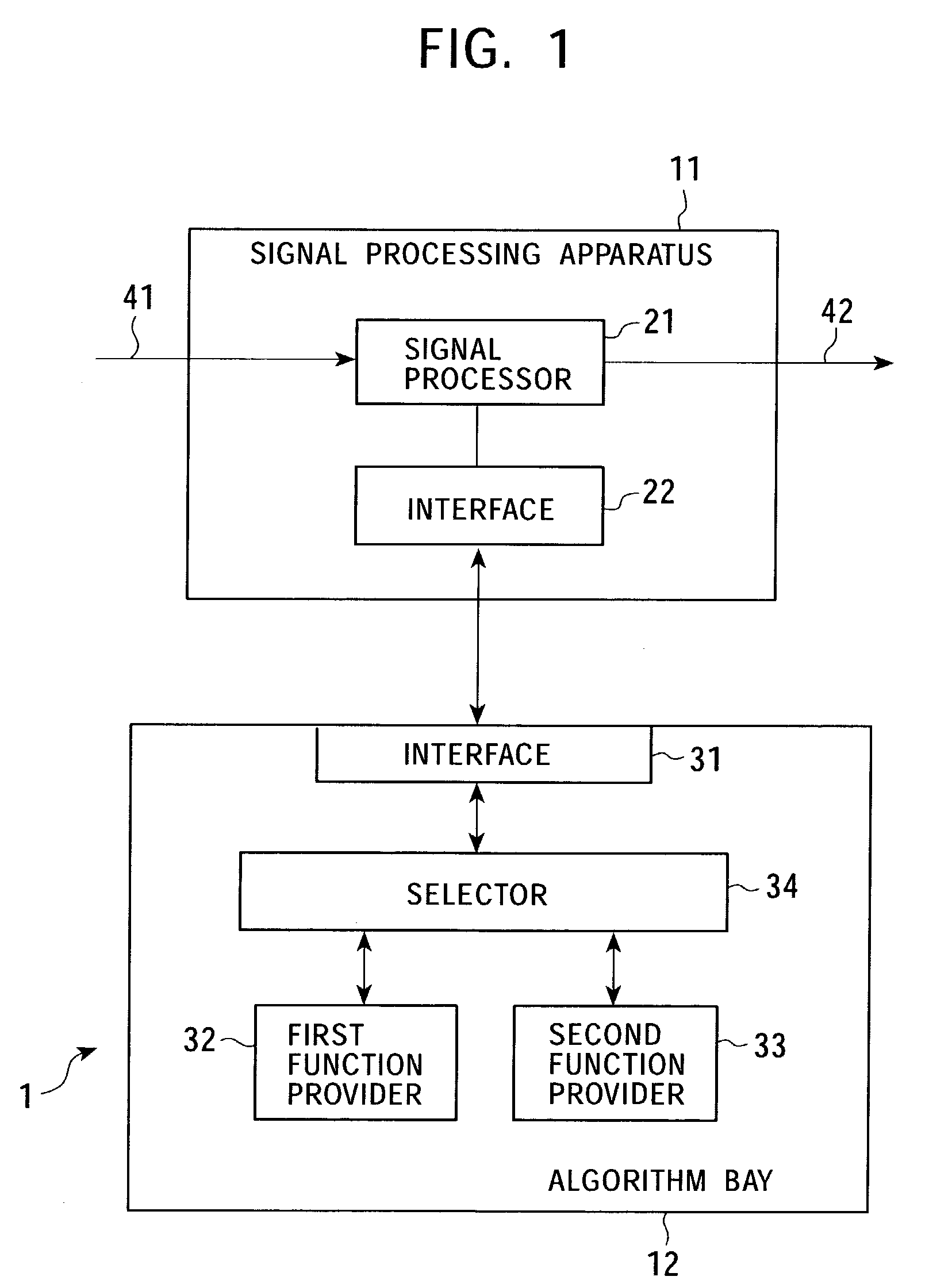
[0154]FIG. 4 is a block diagram schematically illustrating the signal processing system 1 according to the first embodiment of the present invention. The same elements as those shown in FIG. 1 are designated with like reference numerals.

[0155]In the first embodiment, the signal processor 21 converts the input signal 41, which serves as a composite signal, into component signals, and outputs them as the output signal 42.

[0156]More specifically, the signal processor 21 includes, as shown in FIG. 4, a controller 51 for controlling the overall processing of the signal processor 21, and a ⅓ converter 52 for converting the input signal 41, which serves as a composite signal, into component signals.

[0157]The component signals consist of three elements, for example, a luminance signal component (Y) and two chrominance signal components (blue-luminance (B-Y) signal component and red-luminance (R-Y) signal component), or a red signal component (R), a green signal component (G), and a blue sig...

second embodiment

[0224]FIG. 7 is a block diagram schematically illustrating the signal processing system 1 according to the second embodiment of the present invention. The same elements as those shown in FIG. 4 are designated with like reference numerals.

[0225]The structure of the signal processor 21 of the signal processing apparatus 11 shown in FIG. 7 is basically similar to the counterpart shown in FIG. 4, except that the interface 22 is a wireless interface, namely, wireless connection is established between the signal processing apparatus 11 and the algorithm bay 12.

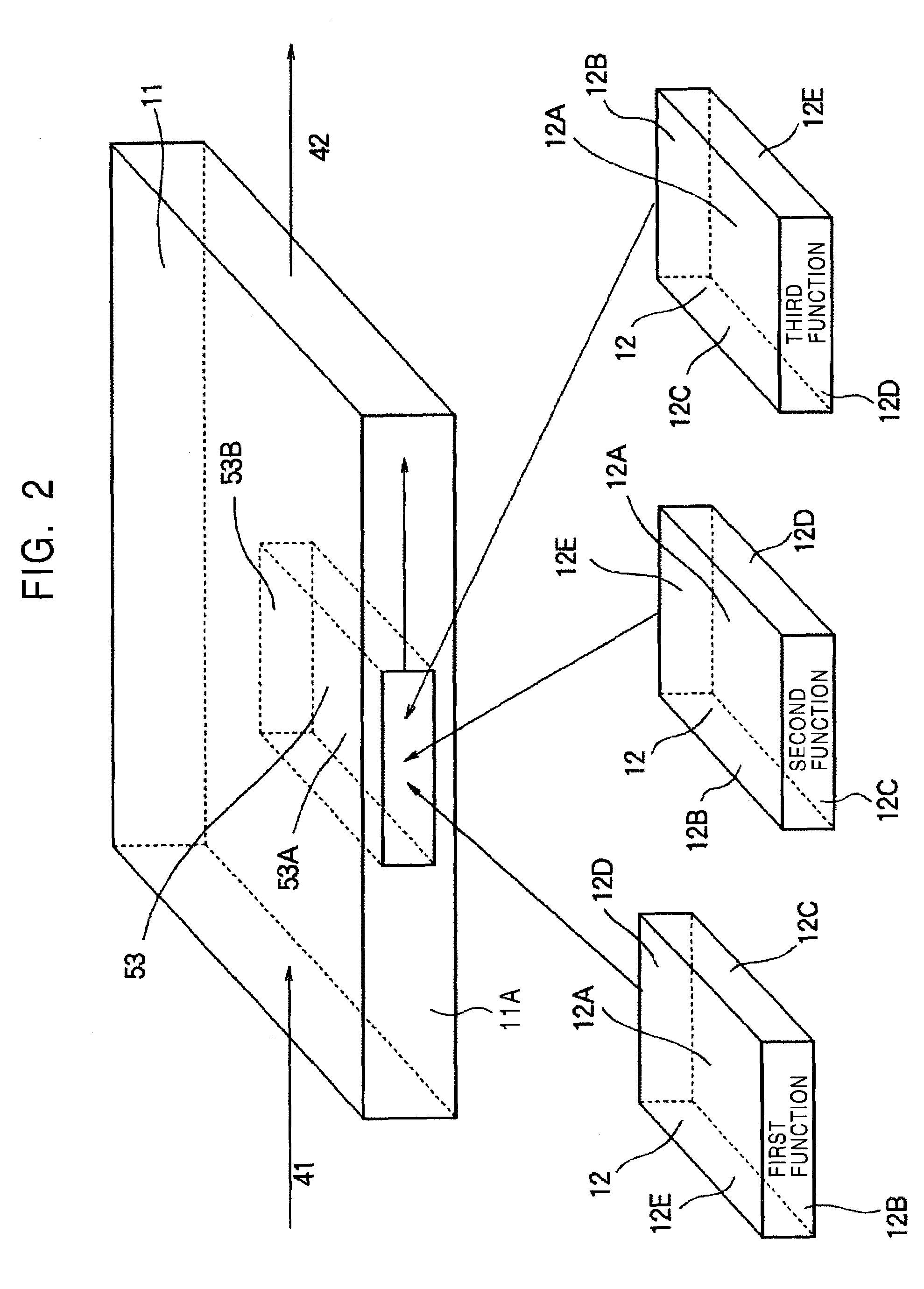
[0226]Accordingly, as stated above, in the first embodiment (FIG. 4), the connection mode of the algorithm bay 12 with the signal processing apparatus 11 is determined by the insertion direction of the algorithm bay 12 to the signal processing apparatus 11. However, in the second embodiment (FIG. 7), the connection mode of the algorithm bay 12 with the signal processing apparatus 11 is determined, as shown in FIG. 3, by the wireless...

third embodiment

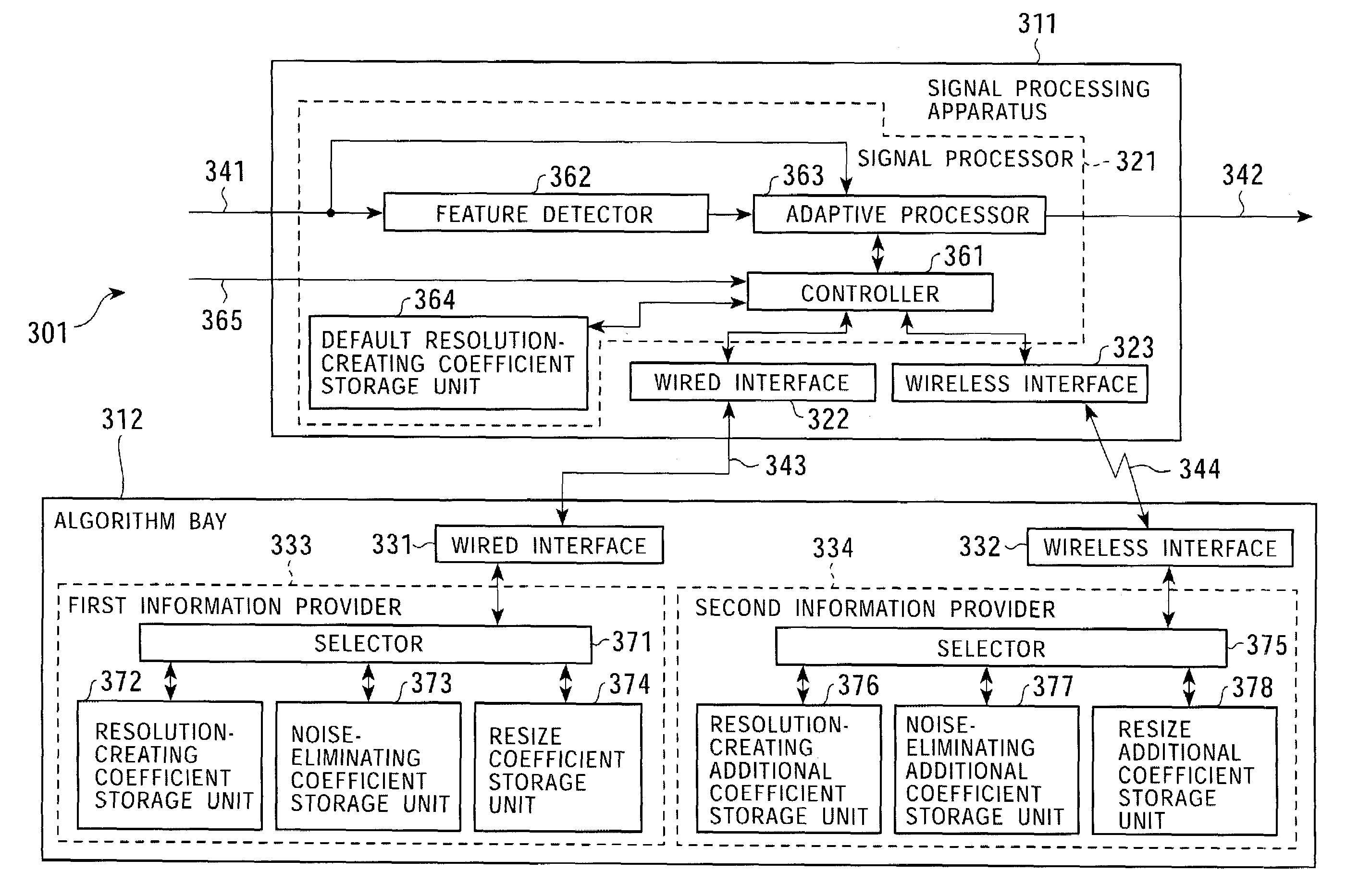
[0243]In the first and second embodiments, by using the signal processing functions provided for the signal processing apparatus 11, signals on which classification adaptive processing is performed by the algorithm bay 12 are output. That is, the functions of the signal processing apparatus 11 are switched by changing the tap coefficients used for the classification adaptive processing (by changing the functions of the classification adaptive processing) of the algorithm bay 12 according to the connection mode of the algorithm bay 12 with the signal processing apparatus 11.

[0244]In the third and fourth embodiments, the connection modes of the algorithm bay 2 with the signal processing apparatus 11 are related to cooperative devices. The cooperative device is specified by the connection mode, and then, the signal processing function of the signal processing apparatus 11 is changed to the function provided for the specified cooperative device.

[0245]FIG. 9 is a block diagram schematica...


PUM

PropertyMeasurementUnit
electricallyaaaaaaaaaa
signal processingaaaaaaaaaa
wireless communication distanceaaaaaaaaaa

Abstract

When an algorithm bay is connected to a signal processing apparatus according to a first connection mode, a selector of the algorithm bay selects and sets a first function provided by a first function provider as the signal processing function of the signal processing apparatus. According to a second connection mode, the selector selects and sets a second function provided by a second function provider as the signal processing function Also, a first information provider of an algorithm bay may supply a signal indicating first information to a signal processor of a signal processing apparatus via a wired interface of the algorithm bay, a wired connection, and a wired interface of the signal processing apparatus. Similarly, a second information provider of the algorithm bay supplies a signal indicating second information for changing the signal processing function of the signal processor to the signal processor.

Description

BACKGROUND OF THE INVENTION[0001]1. Field of the Invention[0002]The present invention relates to signal processing systems and methods, signal processing apparatuses and methods, recording media, and programs. More particularly, the invention relates to a signal processing system and method and a signal processing apparatus and method in which a plurality of signal processing functions provided for the signal processing apparatus can be easily selected and utilized. The invention also pertains to a program implementing the above-described method and to a recording medium storing such a program.[0003]The invention further relates to a signal processing system and method and a signal processing apparatus and method in which updated information for changing signal processing functions can be provided while maintaining security. The invention also pertains to a program implementing the above-described method and to a recording medium storing such a program.[0004]2. Description of the Re...

Claims


Application Information

Patent Timeline
Patent Type & Authority Patents(United States)
IPC IPC(8): H04N7/16H04N11/20H04N7/01G06F13/00G11B20/10
CPCH04N7/0125G11B20/0021G11B20/0071H04N7/0145G11B20/10H04N21/436H04N21/4363G06F13/00
Inventor KONDO, TETSUJIROTANGE, AKIRA
Owner SONY CORP
Why Eureka
Try Eureka