Liquid vapor separator

a technology of liquid vapor separator and separator, which is applied in the direction of liquid fuel feeder, condensed fuel collection/return, non-fuel substance addition to fuel, etc., can solve the problems of damage to the operation of the fuel vapor filter, and achieve the effect of fuel droplets

Active Publication Date: 2010-04-13
KAUTEX TEXTRON
View PDF11 Cites 38 Cited by
  • Summary
  • Abstract
  • Description
  • Claims
  • Application Information

AI Technical Summary

Benefits of technology

[0007]According to the present invention there is provided a liquid vapor separator (LVS) for a fuel system of an automobile, comprising a filler neck connected to a fuel tank, and a vapor line providing fluid flow communication between said fuel tank and a fuel vapor filter; said liquid vapor separator comprising a body having an inlet in fluid communication with an outlet of said fuel tank via a first portion of said vapor line, an outlet in fluid communication with said fuel vapor filter via a second portion of said vapor line, and a draining port providing fluid communication between said body and said filler head, wherein said body is adapted to receive fuel vapor and droplets from said fuel tank through said inlet, and being so constructed as to channel the vapor to said fuel vapor filter through said outlet while diverting the droplets to said filler head through said draining port, whereby said fuel droplets are prevented from reaching said fuel vapor filter and are redirected back into said fuel tank.

Problems solved by technology

The fuel vapor carried from the fuel system often contains an amount of fuel droplets which may have a damaging effect on the operation of the fuel vapor filter.

Method used


Image

  • Liquid vapor separator
  • Liquid vapor separator
  • Liquid vapor separator

Examples


Embodiment Construction

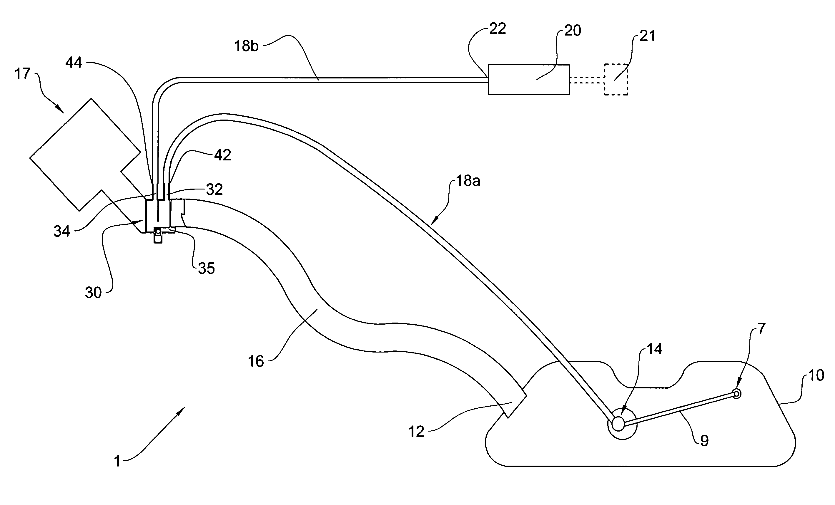
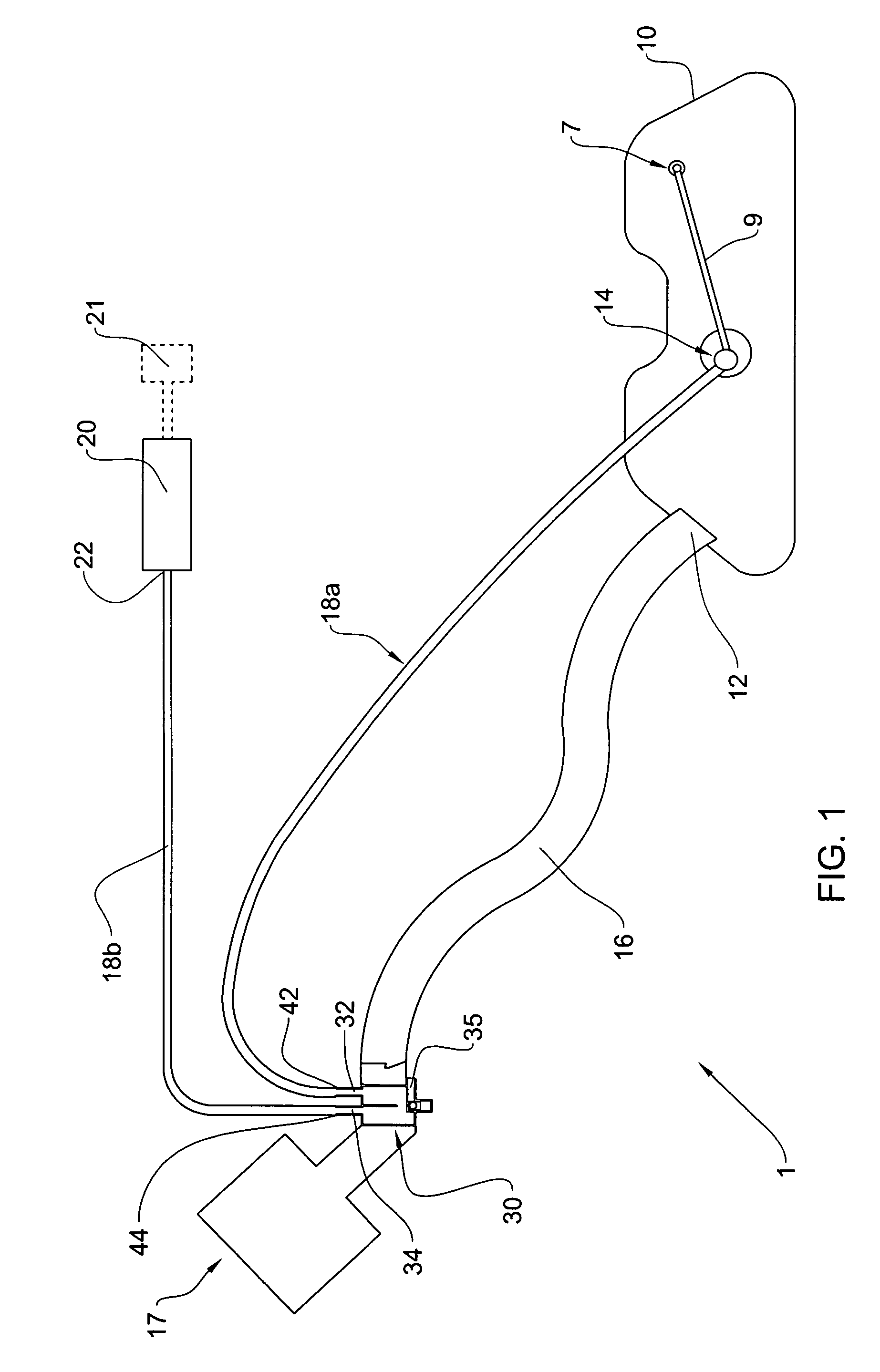
[0065]Referring first to FIG. 1 of the drawings, there is illustrated a schematic illustration of a vehicle's fuel system generally designated 1, fitted with a liquid vapor separator (LVS) according to the present invention generally designated 30. The fuel system shown comprises a fuel tank 10 fitted with a fuel inlet 12 for fuel ingress and a fuel outlet 14 for fuel egress, which is in turn coupled to a valve 7 (e.g. roll over valve) by tubing 9. The fuel inlet 12 is connected to a fuel inlet line 16 (fuel filler neck) fitted with a filler head 17 at its top, for receiving a refueling muzzle 60 (FIG. 4). The fuel outlet 14 is connected to a fuel vapor filter (canister) 20 via a vapor line 18 fitted with liquid vapor separator 30 dividing the vapor line into a first portion 18a and a second portion 18b.

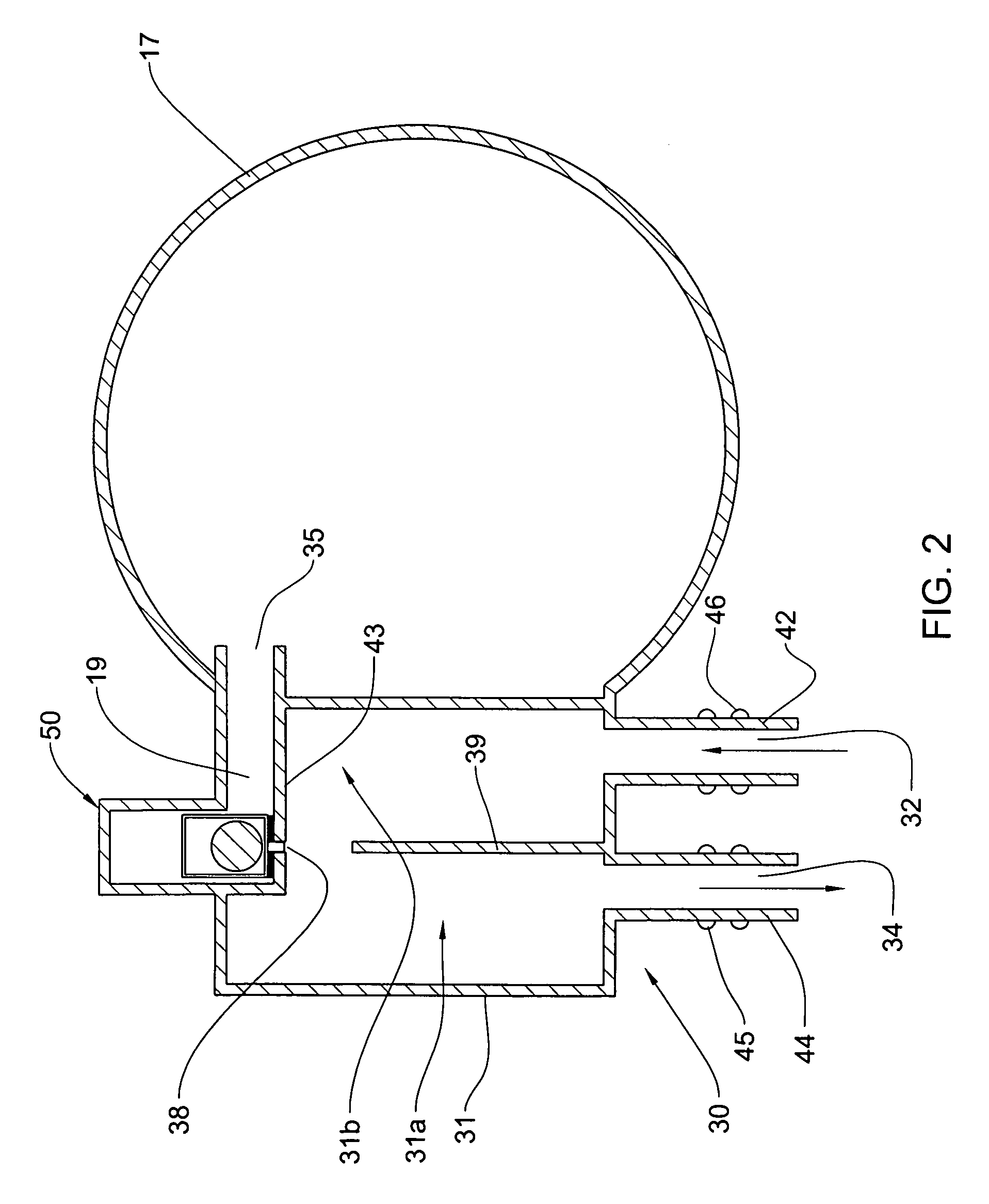
[0066]More particularly and with further reference to FIG. 2, the first portion 18a connects the fuel outlet 14 of the fuel tank 10 with an inlet 32 of the liquid vapor separator 30...


PUM


Abstract

A liquid vapor separator for a vehicle's fuel system, said liquid vapor separator comprising a body having an inlet connectable with a venting system of a fuel tank and a vapor outlet connectable to a fuel vapor treating device, and a condensation space for condensation of fuel droplets, said space being in flow communication with said inlet and with said outlet, and said condensation space extending at or being in flow communication with a filler neck of the fuel system.

Description

[0001]This is a Non-Provisional Application of U.S. Provisional Patent Application No. 60 / 899,406, filed on Feb. 5, 2007, the entire content of which is hereby incorporated by reference in its entirety.FIELD OF THE INVENTION[0002]This invention relates to fuel systems for vehicles and more particularly to a liquid vapor separator (LVS) of the type fitted on a filler-head (also referred to as a filler-neck or a refueling passage) of a filler pipe fitted in a vehicle's fuel system.BACKGROUND OF THE INVENTION[0003]It is known in the field of vehicles and fuel systems, to use a filter canister (fuel vapor filter typically a fuel vapor filter) for fuel vapor exiting the fuel tank. The fuel vapor carried from the fuel system often contains an amount of fuel droplets which may have a damaging effect on the operation of the fuel vapor filter.[0004]A wide variety of solutions has been offered to prevent the introduction of fuel droplets into the fuel vapor filter along with the fuel vapor.[0...

Claims


Application Information

Patent Timeline
Patent Type & Authority Patents(United States)
IPC IPC(8): F02M33/02F02M33/04
CPCB60K15/03504F02M25/0872B60K2015/03509F02M37/0052B60K2015/03576B60K2015/03514B60K15/00B60K15/035F02M25/08
Inventor EHRMAN, MOSHEVULKAN, OMEROLSHANETSKY, VLADIMIRGRUN, KARL-PETERKOUKAN, IBRAHIM
Owner KAUTEX TEXTRON
Why Eureka
Try Eureka