Automatic transmission

a transmission and automatic technology, applied in the direction of gearing control, gear lubrication/cooling, gearing elements, etc., can solve the problems of oil (working fluid, disturbed or obstructed, difficulty in efficiently supplying or returning oil from the air breather chamber to the transmission rotating part, etc., and achieve the effect of efficient supply

Inactive Publication Date: 2008-02-21
JATCO LTD
View PDF5 Cites 30 Cited by
  • Summary
  • Abstract
  • Description
  • Claims
  • Application Information

AI Technical Summary

Benefits of technology

[0009]It is, therefore, in view of the previously-described disadvantages of the prior art, an object of the invention to provide an automatic transmission capable of efficiently supplying oil, separated from gas (air) within an ai

Problems solved by technology

However, there is a possibility that the oil (working fluid), which is separated from the gas (air) within the air breather chamber and then drips through the air-breather opening, is disturbed or obstructed by the previously-noted baffle plate, provided between the transmission ro

Method used


Image

  • Automatic transmission
  • Automatic transmission
  • Automatic transmission

Examples


Embodiment Construction

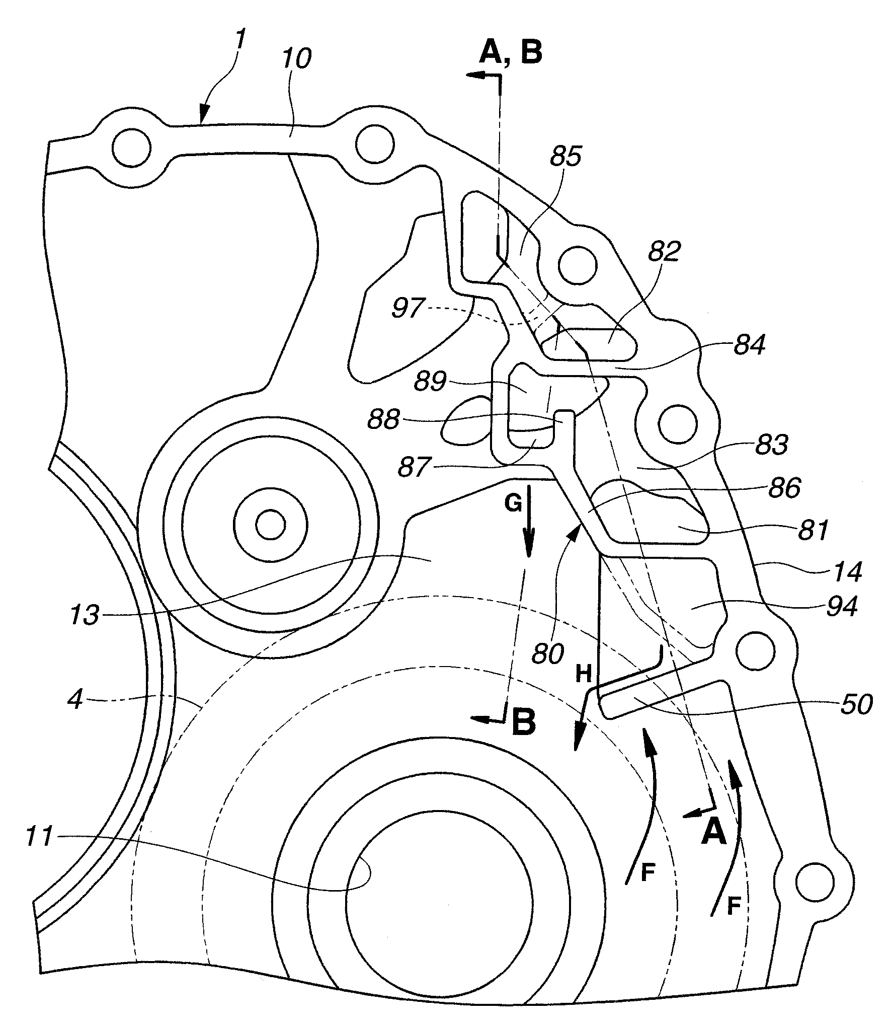
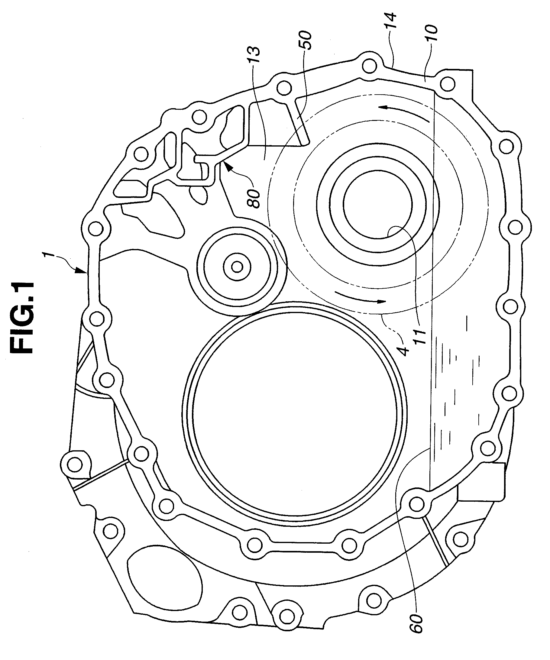
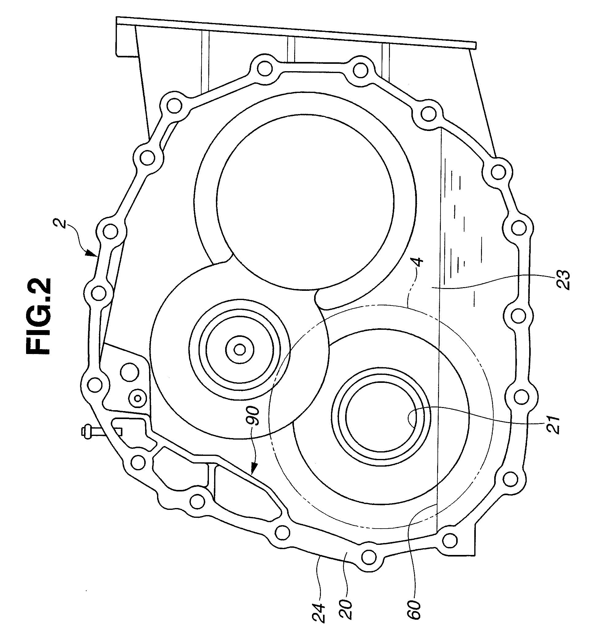
[0020]Referring now to the drawings, particularly to FIGS. 1-3, the air-breather equipped automatic transmission of the embodiment is exemplified in a continuously variable transaxle (CVT), which uses a torque converter. The casing assembly of the automatic transmission is constructed by a converter housing (a bell housing) 1 and a transmission case 2, integrally connected to each other with their mating faces. FIG. 1 is a diagrammatic view of converter housing 1 as viewed from the converter-housing side mating face 10, FIG. 2 is a diagrammatic view of transmission case 2 as viewed from the transmission-case side mating face 20, and FIG. 3 is the side view of the automatic transmission (CVT).

[0021]Additionally, as can be seen from the partial cutaway view of FIG. 3, a part of the side face of converter housing 1 and a part of the side face of transmission case 2 are cut out so as to clearly show an air breather chamber (a converter-housing side air breather chamber 80 and a transmis...


PUM


Abstract

In an automatic transmission having an air breather chamber for separating oil and air, entering the air breather chamber as oil bubbles, a shielding rib is located below an air-breather opening serving as an inlet-and-return port, for preventing oil, stored in a transmission casing assembly and splashed by rotary motion of a transmission rotating component part, from directly reaching the air-breather opening. An upside of the shielding rib is configured to be inclined downwardly with respect to a horizontal line in such a manner as to be oriented toward the transmission rotating component part, for receiving oil dripping through the air-breather opening with the upside of the shielding rib and for rapidly delivering the received oil toward the transmission rotating component part, using the inclined upside of the shielding rib.

Description

TECHNICAL FIELD[0001]The present invention relates to an automatic transmission having an air breather (an air breathing mechanism).BACKGROUND ART[0002]As is generally known, in automatic transmissions capable of automatically executing both upshifting and downshifting, a predetermined amount of oil (working fluid) is stored in a transmission casing assembly. In order to prevent actual contact between any of moving metal surfaces, the oil is supplied to moving or rotating transmission parts, such as bearing parts or gears in meshed-engagement. In multi-disc type automatic transmissions, friction elements are selectively engaged (applied) or disengaged (released) by way of hydraulic pressure application or hydraulic pressure release, so as to achieve a desired shift step. In belt-drive continuously variable transmissions (CVTs), each of which uses an endless drive belt, such as an endless segmented steel belt, running in a pair of variable-width pulleys, namely primary and secondary—...

Claims


Application Information

Patent Timeline
IPC IPC(8): F16H57/04F16H57/02F16H57/027
CPCF16H57/027Y10T74/19991Y10T74/2186F16H57/0421F16H57/04
Inventor YASUI, KENJIROSATOU, NAOTO
Owner JATCO LTD
Why Eureka
Try Eureka