
Sheet feeding cassette and image forming apparatus

a technology of image forming apparatus and feeding cassette, which is applied in the direction of thin material processing, instruments, article separation, etc., can solve the problems of unnatural user applied force, inability to use the fence, and inability to reduce the declination of the fence, so as to improve the fence and the effect of improving the quality of the fen

Active Publication Date: 2010-04-13
RICOH KK
View PDF11 Cites 18 Cited by
  • Summary
  • Abstract
  • Description
  • Claims
  • Application Information

AI Technical Summary

Benefits of technology

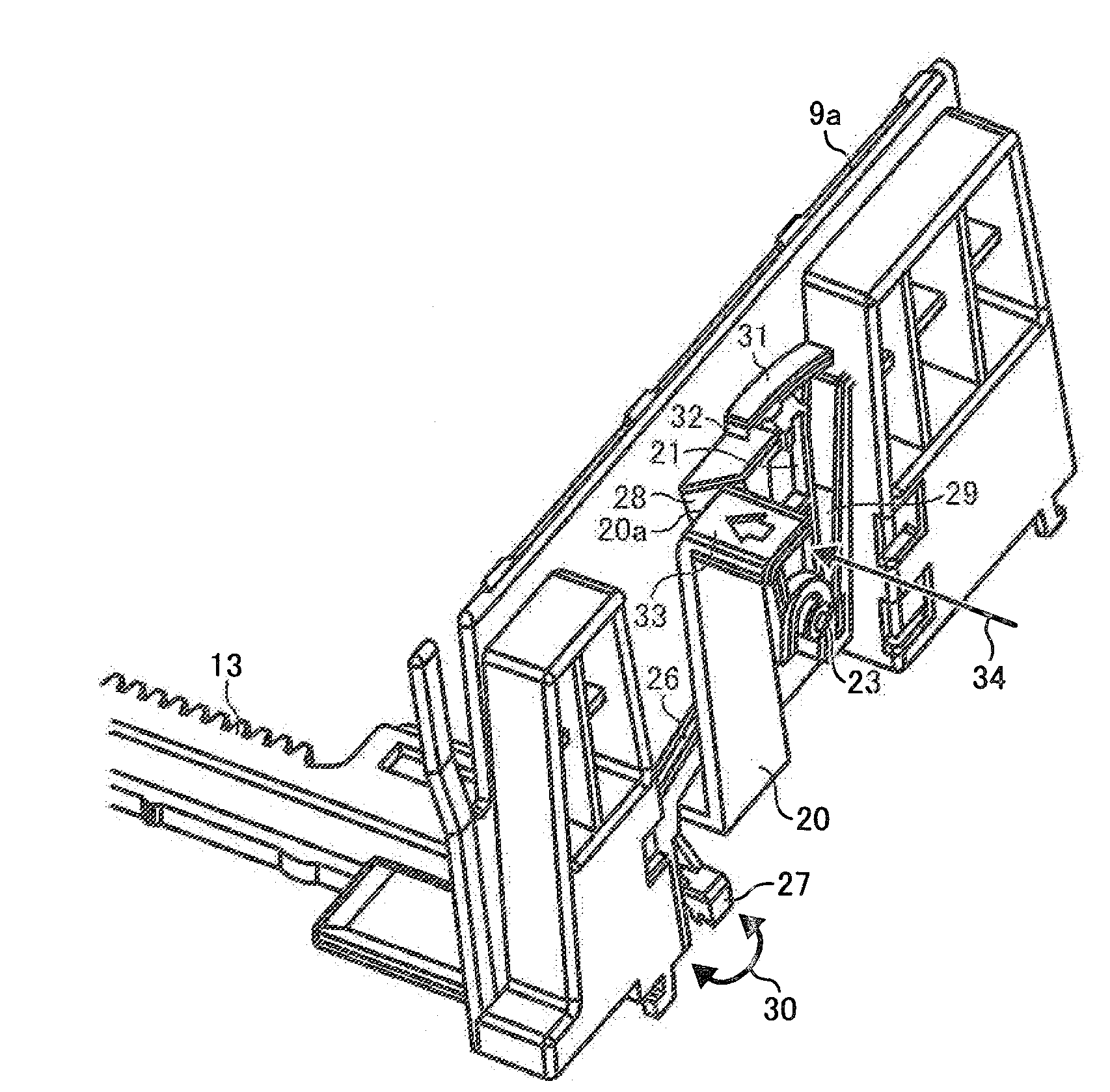
The present invention provides a sheet feeding cassette and an image forming apparatus that operate smoothly by corresponding to the pushing direction of the lever with the moving direction of the fence and by lightening the force needed to move the lever to release the fence. The invention includes a fixing portion with a tooth portion that engages with a trench to fix a position of the fence, a lever portion that contacts the fixing portion to disengage the tooth portion from the trench, and a cover to improve user-friendliness. The invention also includes a biasing device to securely fix the fence, a guide portion to restrict deflection of the lever, and a plurality of tooth portions for stable operation of fixing and releasing the fence.

Problems solved by technology

However, this sheet feeding cassette configuration has drawbacks because the pushing direction of the button and the moving direction of the fence are in discord.
That is, use of the fence requires an unnatural user applied force to adjust the fence to an accurate position.
However, as discussed above, the sheet feeding cassette has drawbacks because the releasing direction of the fixing portion and the moving direction of the fence are in discord.
Consequently, an unnatural force is required to adjust the location of the fence to an accurate position.
However, this configuration has drawbacks because a trench wall exists in the rotating direction of the tooth portion and the tooth portion strikes against the wall.
Consequently, friction may occur and additional effort is required by the user to operate the fence.

Method used


Image

  • Sheet feeding cassette and image forming apparatus
  • Sheet feeding cassette and image forming apparatus
  • Sheet feeding cassette and image forming apparatus

Examples


first embodiment

[0044]the present invention is described in detail referring to the FIGS. 1-4 and 7-11.

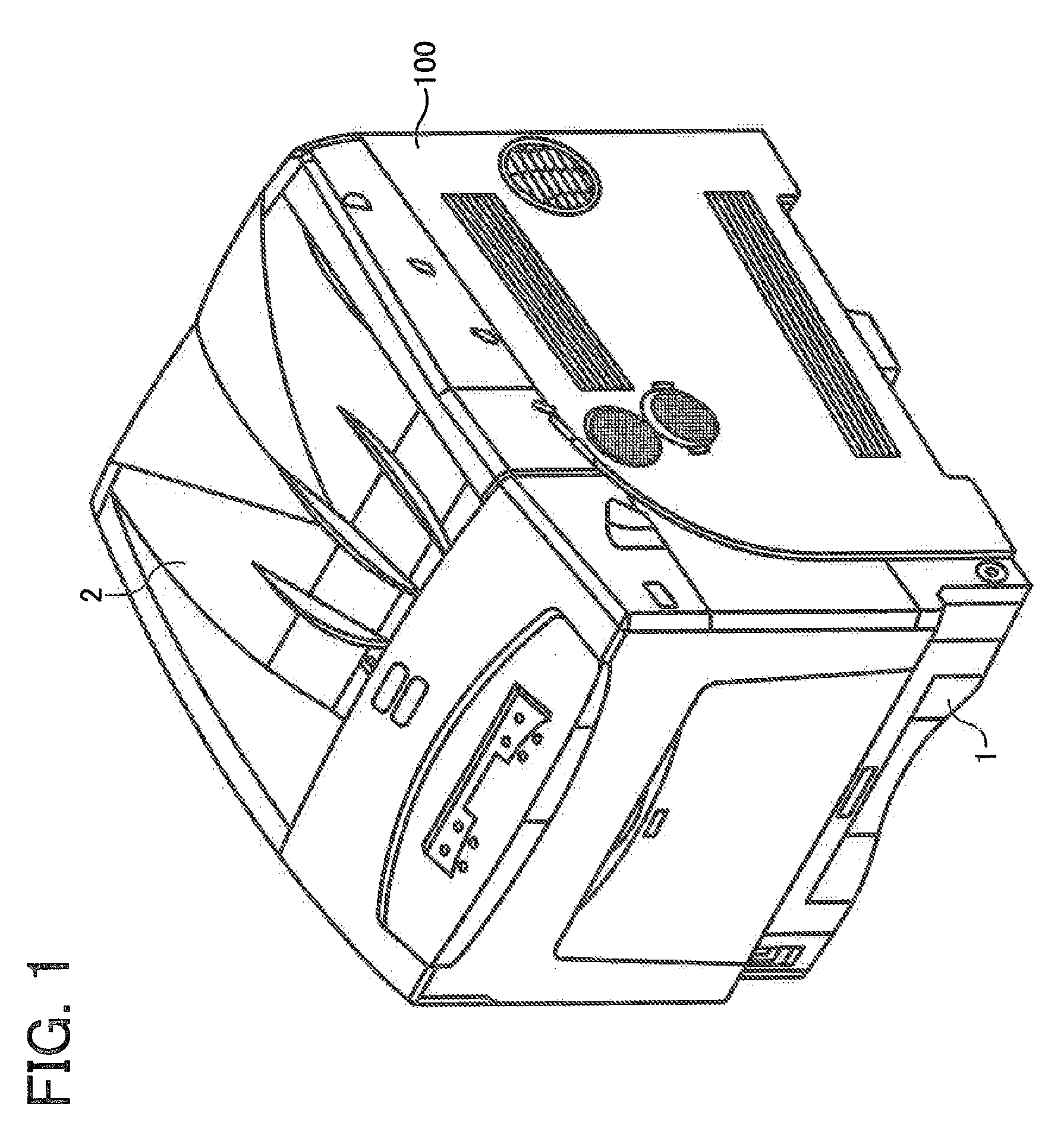
[0045]FIG. 1 is a perspective view of a laser beam printer as an example of an image forming apparatus according to an embodiment of the present invention. A sheet feeding cassette 1 is provided in a body portion a main body case 100 of the printer. In a top surface of the main body case 100, a sheet discharging tray 2 is formed. The sheet (S), having a fixed toner image provided thereon, is discharged and stacked on the sheet discharging tray 2.

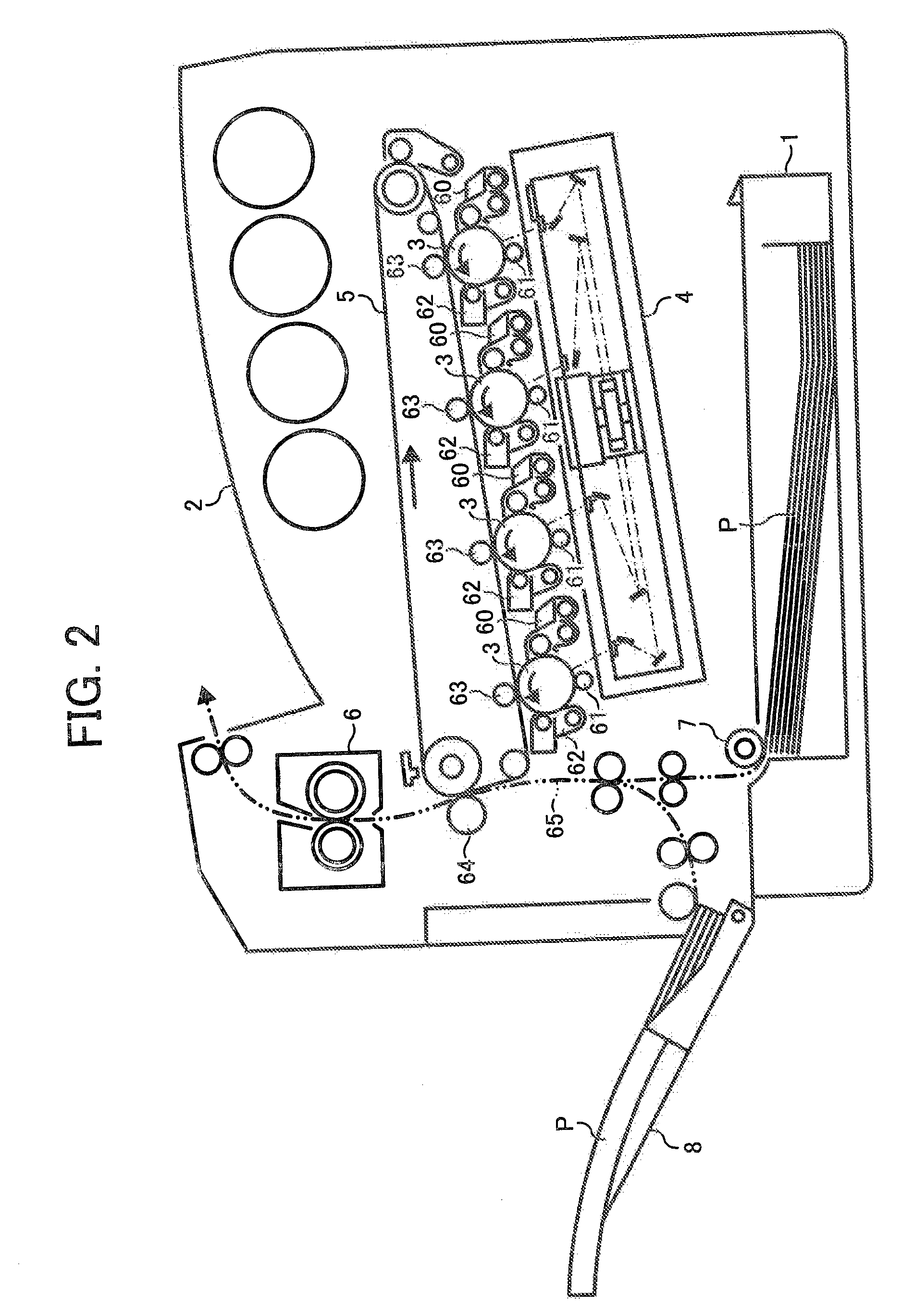
[0046]FIG. 2 is a cross-section view of FIG. 1 showing an overall configuration of the laser beam printer according to an embodiment of the present invention.

[0047]The image forming apparatus includes a drum shaped photoreceptor 3, a charging device 61, a developing device 60, a transfer belt 5, a cleaning device 62, and a fixing device 6 which collectively form a device for forming an image which is provided for each of the colors (yellow, magenta, cyan, ...

second embodiment

[0068]As illustrated in FIG. 12, the feature of the second embodiment is a cover 38 that covers entirely the fixing portion 21 to improve aspects of the fence 9a, 9b. The cover 38 is large enough to cover the fixing portion and the lever entirely except for the knob 33. The cover 38 improves aspects of the sheet feeding cassette 1 because the cover 38 covers a rotating structure of the fixing portion 21. The cover 38 is attached to the side fence 9a to prevent hooks 41 (illustrated in FIG. 15) from falling that are formed integrally to the cover 38.

[0069]As illustrated in FIG. 13, a guide member 39 is provided on the top of the cover 38 to regulate the movement perpendicular to the direction of the movement of the lever 20 (the direction of the movement of the lever 20 is show as an arrow 40).

[0070]A guide member 39 regulates a meandering motion of the lever 20 toward the arrow 40. The slope portion 28 contacts the same position of the inner portion 20a of the lever. Consequently, t...

third embodiment

[0072]As illustrated in FIG. 14, the feature of the third embodiment is a convex portion 45 which forms part of the arm 26 of the fixing portion 21 via the tooth portion 27. A concave portion 46 is provided on the side fence 9a to engage the convex portion 45. Specifically, the position of the convex portion 45 correlates to the position of the concave portion 46. The convex portion 45 engages the concave portion 46 to engage the tooth portion 27 with the trench 19, which has an interspace between the bottom of the tooth portion 27 and the bottom 19b.

[0073]In FIG. 14, the convex portion 45 and the concave portion 46 are shown separately for easy comprehension.

[0074]In case the user accidentally closes the fences 9a, 9b without releasing the fixing portion 21, the engagement between the convex portion 45 and the concave portion 46 can withstand the closing force of the side fences 9a, 9b. Specifically, the force of closing the side fence 9a, 9b is minimally exerted on the tooth port...


PUM


Abstract

A sheet feeding cassette, including a main body of the sheet feeding cassette accommodating sheets having a trench; a fence movably attached to the main body configured to define a setting position of the sheets; a fixing portion included in the fence that includes a tooth portion engaging with the trench and turns to substantially perpendicular direction of the moving direction of the fence; a lever portion included in the fence that is possible to move corresponding to the moving direction of the fence and the lever portion configured to rotate the fixing portion by moving of the lever portion.

Description

CROSS-REFERENCE TO RELATED APPLICATIONS[0001]The present application claims priority to Japanese Patent Application No. 2006-038136 filed in the Japanese Patent Office on Feb. 15, 1006, the disclosure of which is incorporated herein by reference.BACKGROUND OF THE INVENTION[0002]1. Field of the Invention[0003]The present invention relates to a sheet feeding cassette accommodating sheets of a recording medium (e.g., paper) and an image forming apparatus including the sheet feeding cassette, for example, a copier, facsimile, plotter, or printing machine.[0004]2. Description of the Related Art[0005]In a sheet feeding cassette of an image forming apparatus including a sheet feeding cassette accommodating sheets, a fence (side fence) that defines the position of the sheets perpendicular to a direction of sheet feeding is needed because the accuracy of the position of the fence directly affects a skew angle of the sheet feeding.[0006]It is preferable that a light force is required to move ...

Claims


Application Information

Patent Timeline
Patent Type & Authority Patents(United States)
IPC IPC(8): B65H1/04
CPCG03G15/6502G03G2215/00565G03G2215/00383
Inventor NAKAMURA, MITSUTAKA
Owner RICOH KK
Learn More