Plasma display apparatus using filter

a technology of plasma display and filter, which is applied in the direction of static indicating devices, identification means, instruments, etc., can solve the problems of degrading the brightness of pdp, and achieve the effect of improving the bright room contrast of the plasma display panel and preventing the reflection of ligh

Inactive Publication Date: 2010-04-13
LG ELECTRONICS INC
View PDF11 Cites 5 Cited by
  • Summary
  • Abstract
  • Description
  • Claims
  • Application Information

AI Technical Summary

Benefits of technology

[0006]Accordingly, the present invention has been made in view of the above problems occurring in the related art, and it is an object of the present invention to provide a plasma display apparatus including an external light blocking sheet which effectively blocks the external light which is injected to the plasma display panel to prevent the reflection of the light and innovatively improves the bright room contrast of the plasma display panel with the brightness of the panel.

Problems solved by technology

However, there is a problem in that, as to PDP, when a black image is implemented, the external light is reflected in the front side of panel of PDP due to the phosphor of white color which is exposed to the lower substrate of the panel, thereafter, the black image is recognized as a dark color of the bright color series, thereby the bright room contrast of PDP is degraded.

Method used


Image

  • Plasma display apparatus using filter
  • Plasma display apparatus using filter
  • Plasma display apparatus using filter

Examples


first embodiment

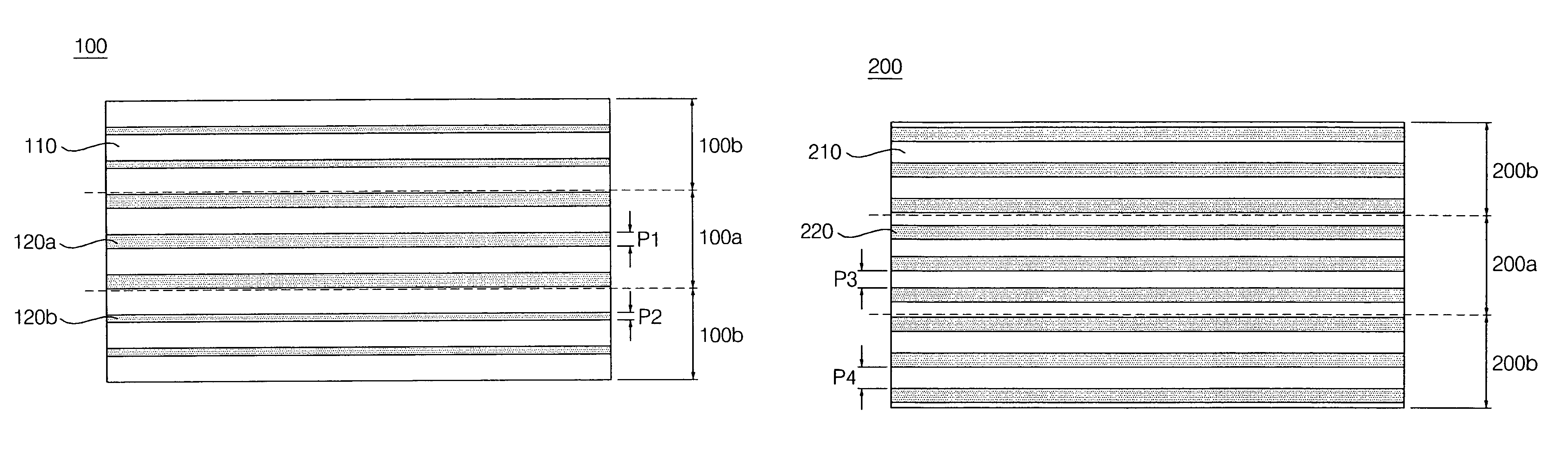
[0063]FIG. 4 is a drawing which shows the configuration of an external light block sheet according to the invention.

[0064]Referring to FIG. 4, the external light blocking sheet 100 of the invention is comprised of a base portion 110 and a plurality of pattern portions 120a, 120b formed in the base portion 110 in series. It is preferable that the thickness of the external light blocking sheet 100 ranges from 20 μm to 250 μm in consideration of the height of the pattern portions 120a, 120b and the transmittance ratio of the light.

[0065]The base portion 110 is formed with a transparent plastic material having a predetermined refractive index. For example, it is most desirable to use a resin formed with ultraviolet ray UV hardening mode, however, if the material is transparent and can be thin shaped like glass, it can be used.

[0066]Pattern portion 120a, 120b are formed between the base portions 110 with a predetermined gap. At this time, pattern portion 120a, 120b has a predetermined ga...

second embodiment

[0084]In the meantime, in the invention, it was illustrated that the structure of the external light blocking sheet is divided into three parts with the central area and the edge area of the external light blocking sheet. However, the gap between the adjacent pattern portions increases or can be different from the center to the upper part or the lower part. In FIG. 6 to FIG. 7b, all the line width of the pattern portion are set to be identical, while the line width can be differently formed in at least one of a plurality of pattern portions.

[0085]FIG. 8 is a drawing which shows an embodiment of the configuration of an external light block sheet according to the invention.

[0086]Referring to FIG. 8, the external light blocking sheet 300 according to the invention includes a base portion 310 and a pattern portion 320. The gap between the pattern portions 320 formed in the central area 300a of the external light blocking sheet 300 is smaller than the gap between the pattern portions 320...


PUM


Abstract

The present invention relates to a plasma display apparatus including an external light blocking sheet which blocks and absorbs the external light injected from the outside, in particular, in which a pattern portion having a predetermined gap and width on a base portion prevents the external light from injecting into the inside of a panel inside, in addition, and permits to efficiently radiate a light emitted from the inside of the panel, thereby, the bright room contrast of PDP can be improved.

Description

BACKGROUND OF THE INVENTION[0001]1. Field of the Invention[0002]The present invention relates to a plasma display apparatus, in particular, to a plasma display apparatus capable of improving the bright room contrast of the panel and maintaining the brightness by installing a filter including an external light blocking sheet which blocks and absorbs the external light on the front side of the panel in order to prevent the light injected from the outside from being reflected in the panel.[0003]2. Description of the Related Art[0004]Plasma display panel (herein after, PDP) is an apparatus which generates a discharge by applying a predetermined voltage to the electrodes installed at the discharge space and displays an image including a characteristic and a graphic by exciting the phosphor with the plasma which is generated in the gaseous discharge, which facilitates the large-size, the light weight and the plane thin shape and provides the broad viewing angle in the up and down directio...

Claims


Application Information

Patent Timeline
Patent Type & Authority Patents(United States)
IPC IPC(8): H01J5/16H01J61/40H01K1/26H01K1/30G02B5/00G02B5/22G09F9/00G09G3/28G09G3/288G09G3/291G09G3/294G09G3/296G09G3/298H05K9/00
CPCH01J11/12H01J11/44H01J2211/444H01J2211/442G02B5/20
Inventor PARK, YUPARK, HUN GUN
Owner LG ELECTRONICS INC
Why Eureka
Try Eureka