Plasma display panel

a technology of display panel and plasma, which is applied in the direction of gas discharge vessel/container, electrode, gas-filled discharge tube, etc., can solve the problems of poor bright room contrast of pdp operating under bright room conditions, and achieve the effect of improving bright room contrast, high opening ratio and convenient manufacturing

Inactive Publication Date: 2007-06-26
SAMSUNG SDI CO LTD
View PDF20 Cites 1 Cited by
  • Summary
  • Abstract
  • Description
  • Claims
  • Application Information

AI Technical Summary

Benefits of technology

[0013]It is also an object of the present invention to provide a design for a PDP that has improved bright room contrast while having a high opening ratio.
[0014]It is further an object of the present invention to provide a design for a PDP that is easy to manufacture.
[0015]It is still an object of the present invention to provide a design for a PDP that has superior luminance characteristics.

Problems solved by technology

However, such a design results in poor bright room contrast of the PDP operating under in bright room conditions because of a low absorption efficiency of outside light.

Method used


Image

  • Plasma display panel
  • Plasma display panel
  • Plasma display panel

Examples


Embodiment Construction

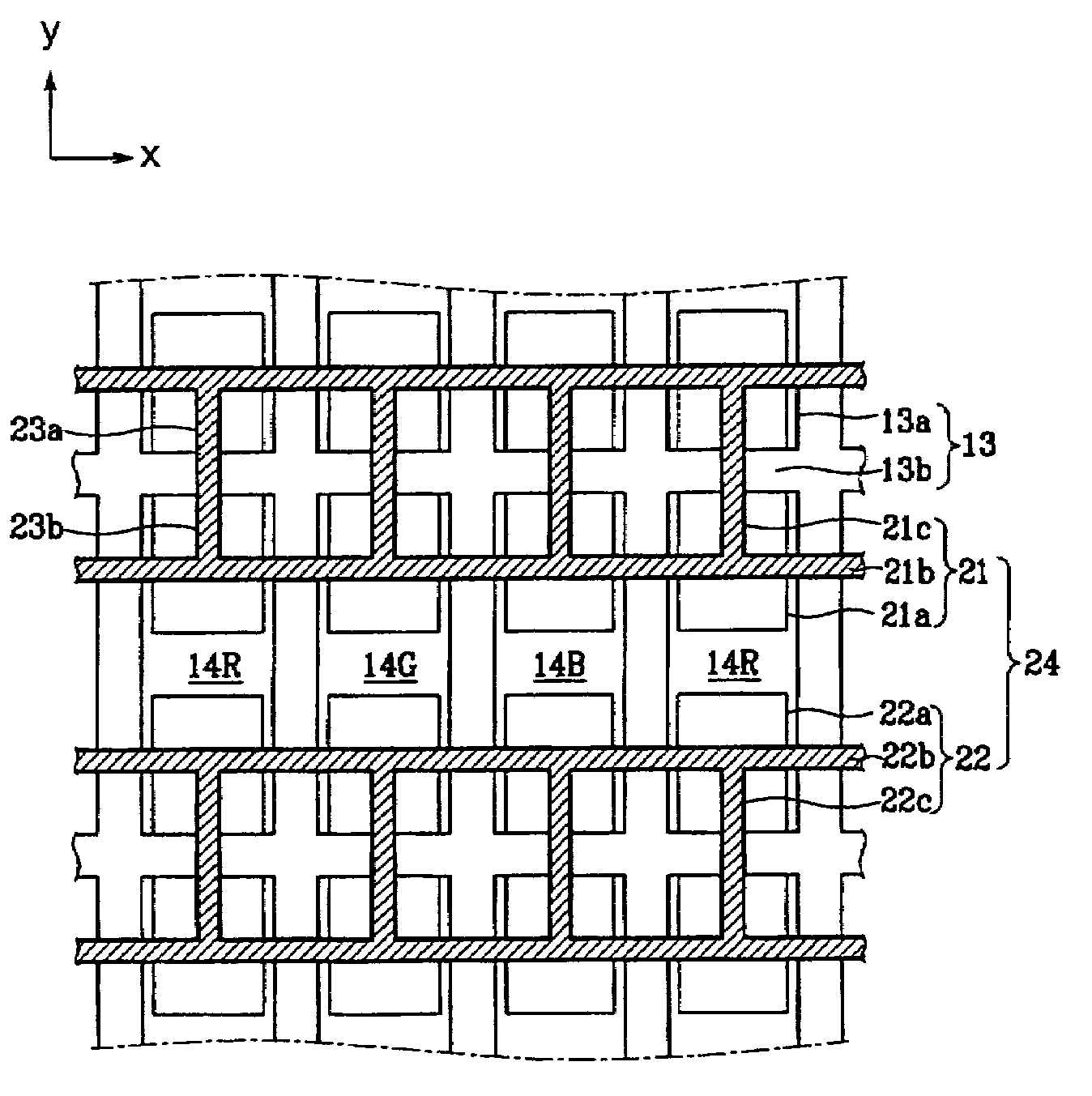
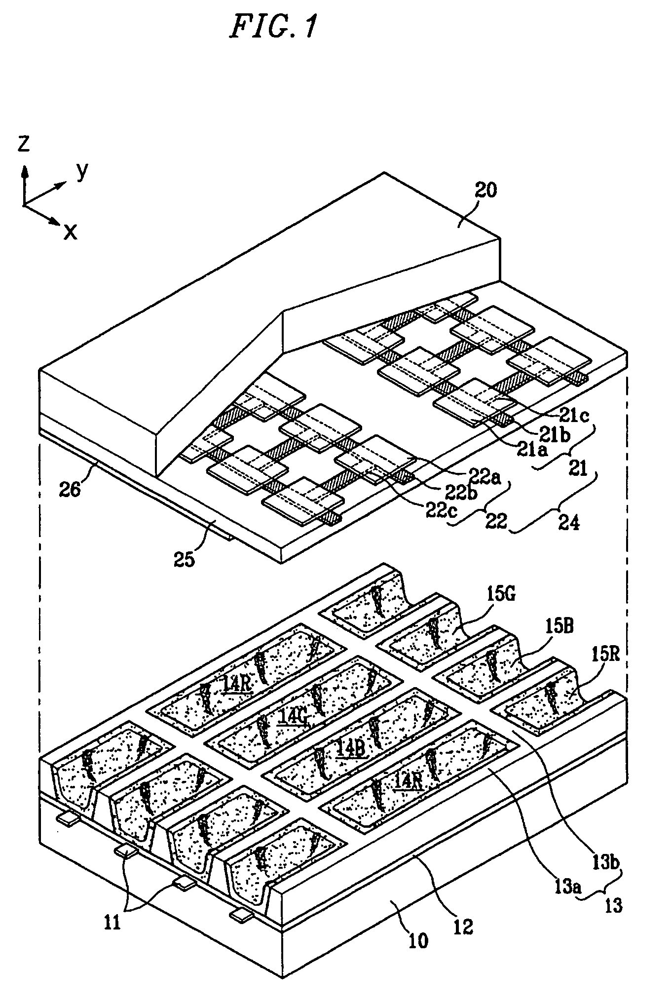
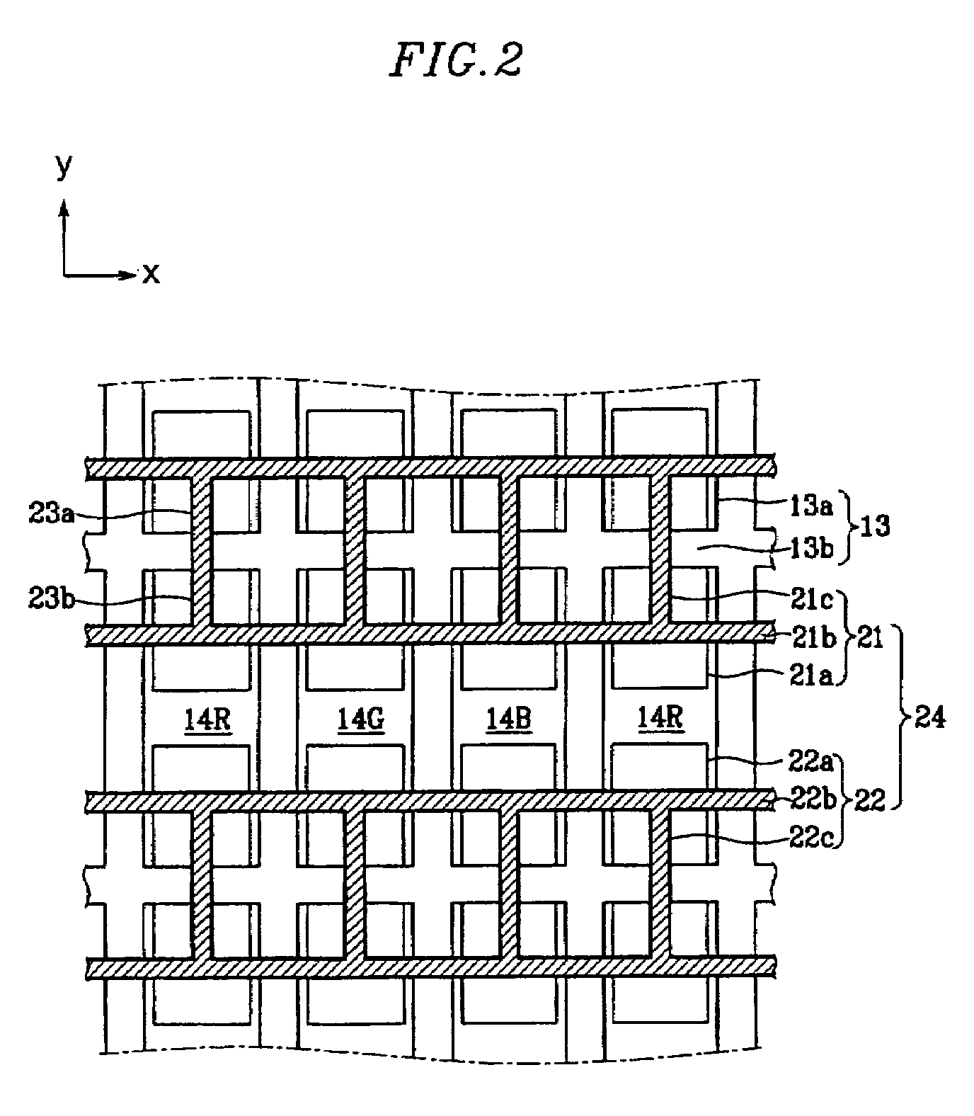
[0025]As illustrated in FIG. 1, a PDP according to the present invention includes a first substrate 10, a second substrate 20 facing the first substrate 10 and spaced apart from the first substrate 10 by a certain distance, and discharge cells 14R, 14G, 14B surrounded by barrier ribs 13, the barrier ribs 13 having a height corresponding to the certain distance between the first substrate 10 and the second substrate 20.

[0026]The barrier ribs 13 include first barrier rib members 13a extending in a first direction (y-direction of the figures) and second barrier rib members 13b extending in a second direction (x-direction of the figures). The barrier ribs 13 are formed in a lattice pattern and independently define the discharge cells 14R, 14G, 14B, the discharge cells 14R, 14G, 14B being filled with a discharge gas. R, G, B (red, green, blue) phosphor layers 15R, 15G, 15B are formed on four sides of the barrier ribs 13 and on the floor (−z end) of the discharge cells 14R, 14G, 14B.

[0027...


PUM


Abstract

A plasma display panel (PDP) with improved bright room contrast while achieving a high opening ratio and high luminance. The PDP includes display electrodes that includes auxiliary electrodes that suppress reflection of incident light off the discharge cells. With address electrodes formed on the rear substrate and the display electrodes formed on the front substrate, auxiliary electrodes connect pairs of display electrodes together. The auxiliary electrodes and the main bus electrodes extend into the discharge cells and reflect the external light. The opaque main bus and auxiliary electrodes are combined with a transparent electrode portion that overlies the main bus and the auxiliary portions to form the display electrodes.

Description

CLAIM OF PRIORITY[0001]This application makes reference to, incorporates the same herein, and claims all benefits accruing under 35 U.S.C. §119 from an application for PLASMA DISPLAY PANEL earlier filed in the Korean Intellectual Property Office on 23 Jun. 2004 and there duly assigned Serial No. 10-2004-0047039.BACKGROUND OF THE INVENTION[0002]1. Field of the Invention[0003]The present invention pertains to a plasma display panel (PDP), and in particular, to a design for a PDP design that results in improved bright room contrast while maintaining a high opening ratio and a high luminance.[0004]2. Description of the Related Art[0005]In general, a PDP is a display device where ultraviolet rays generated during gas discharge excite phosphors to produce a visible image. PDPs have received a lot of attention recently as next generation display devices because of their large screen size, thin depth, and high resolution.[0006]PDPs are classified into direct current (DC) types and alternati...

Claims


Application Information

Patent Timeline
Patent Type & Authority Patents(United States)
IPC IPC(8): H01J17/49H01J11/12H01J11/22H01J11/24H01J11/26H01J11/34H01J11/36H01J11/38H01J11/40H01J11/42H01J11/44H01J11/50
CPCH01J11/12H01J11/24H01J2211/245
Inventor HWANG, EUI-JEONGLEE, TAE-HO
Owner SAMSUNG SDI CO LTD
Why Eureka
Try Eureka