
Filter for a plasma display apparatus

a filter and plasma technology, applied in the direction of instruments, optical elements, incadescent envelopes/vessels, etc., can solve the problems of increasing the weight and cost of the conventional plasma display apparatus, complicated manufacturing process and increasing the weight and cost of the conventional tempered glass filter. , to achieve the effect of reducing weight, increasing bright room contrast, and reducing weigh

Inactive Publication Date: 2008-12-04
SAMSUNG SDI CO LTD
View PDF3 Cites 1 Cited by
  • Summary
  • Abstract
  • Description
  • Claims
  • Application Information

AI Technical Summary

Benefits of technology

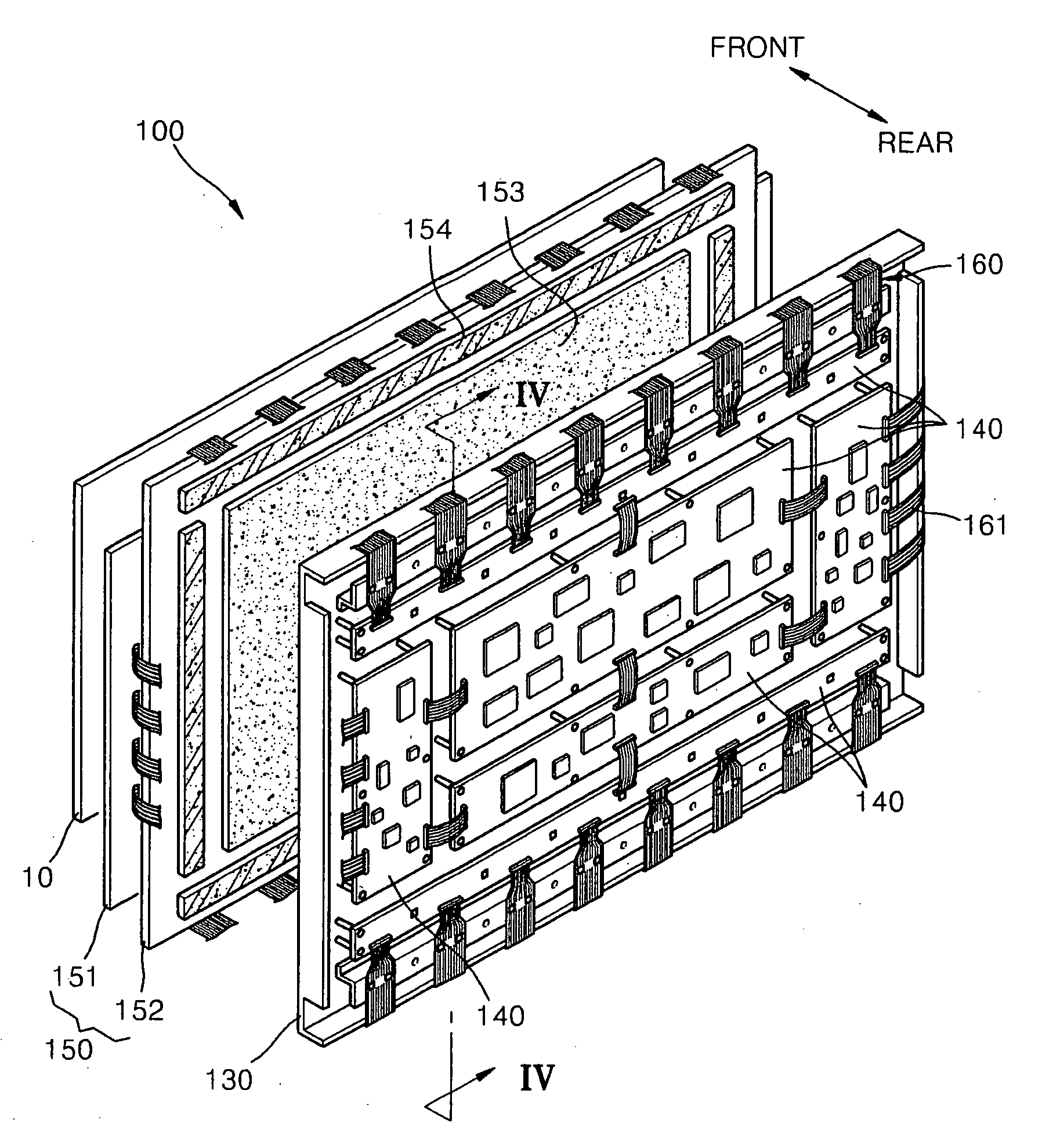
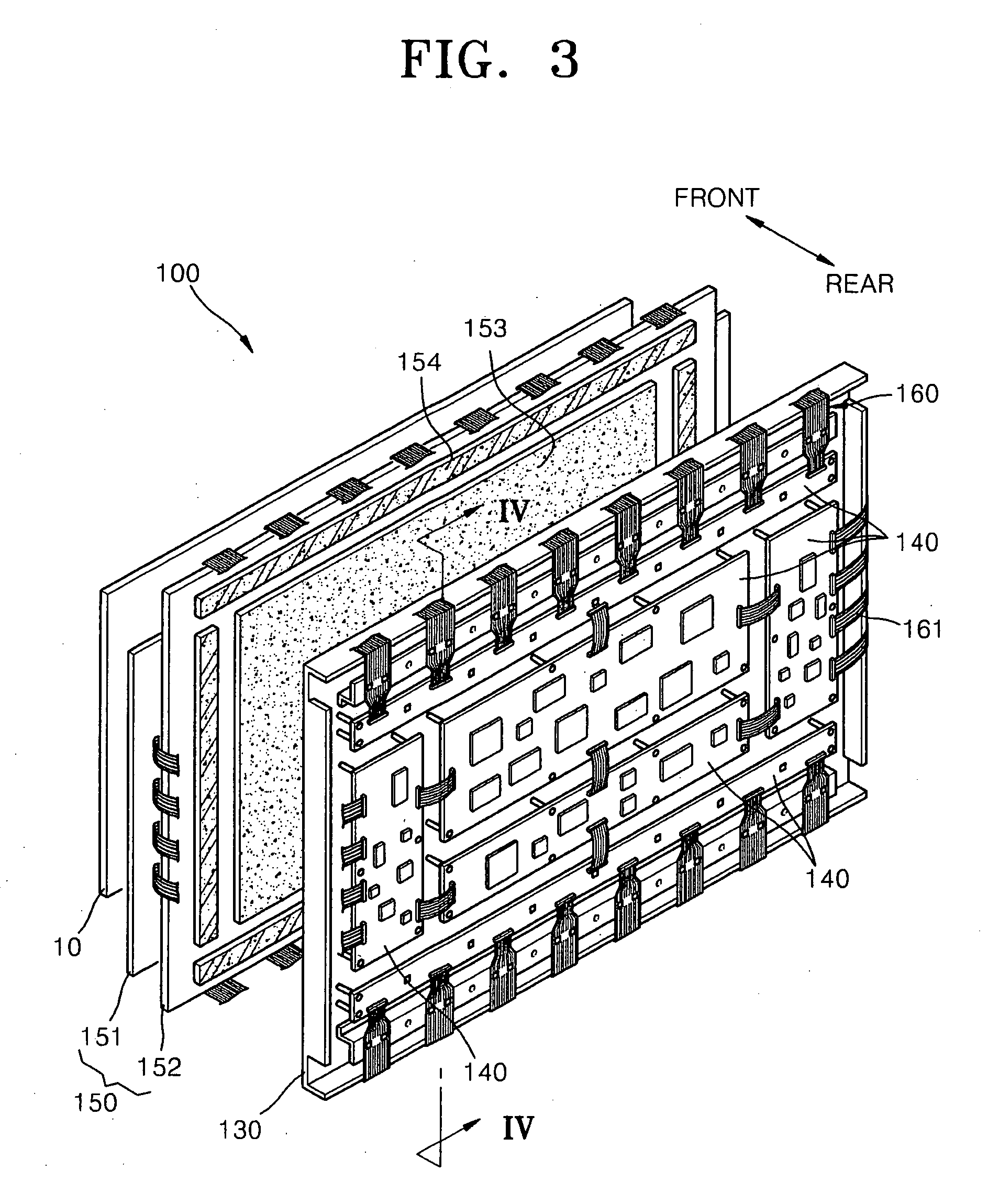
The present invention provides a filter that can prevent a double image, increase bright room contrast, have a reduced weight, and a plasma display apparatus having the filter. The filter includes a base film, a plurality of light absorbing pattern units that are extended on a surface of the base film in predetermined intervals having a stripe shape, and blocking electromagnetic waves, and a reflection prevention layer covering the plurality of light absorbing pattern units. The plurality of light absorbing pattern units may have a polygonal cross-section and may be formed of metal oxide blocking electromagnetic waves. The filter may further include a hard coating layer formed on the reflection prevention layer, an adhesive layer formed on the lower surface of the filter, and a near infrared ray shielding layer formed on the side of the filter. The filter may also include a color correction layer formed on the side of the filter. The display apparatus includes a display panel displaying an image, a driving circuit substrate controlling the display panel, and the filter attached on the front surface of the display panel. The display panel may be a plasma display panel displaying an image using gas discharge.

Problems solved by technology

However, a conventional plasma display apparatus gives a double reflection of an image due to refraction caused by a material difference between a front substrate of a plasma display panel and a conventional tempered glass filter.
Also, the conventional tempered glass filter must have a thickness of approximately 3 mm or more to resist external impact, and thereby increasing weight and cost of the conventional plasma display apparatus.
Furthermore, the conventional tempered glass filter has a very complicated structure including various filters having various functions.
Therefore, the process of manufacturing the conventional tempered glass filter is complicated and costly.

Method used


Image

  • Filter for a plasma display apparatus
  • Filter for a plasma display apparatus
  • Filter for a plasma display apparatus

Examples


Embodiment Construction

[0025]The present invention will now be described more fully with reference to the accompanying drawings, in which exemplary embodiments of the invention are shown. The invention may, however, be embodied in many different forms and should not be construed as being limited to the embodiments set forth herein; rather, these embodiments are provided so that this disclosure will be thorough and complete, and will fully convey the concept of the invention to one skilled in the art. In the drawings, the thickness of layers and region are exaggerated for clarity. Like reference numerals in the drawings denote like elements, and thus their description will be omitted.

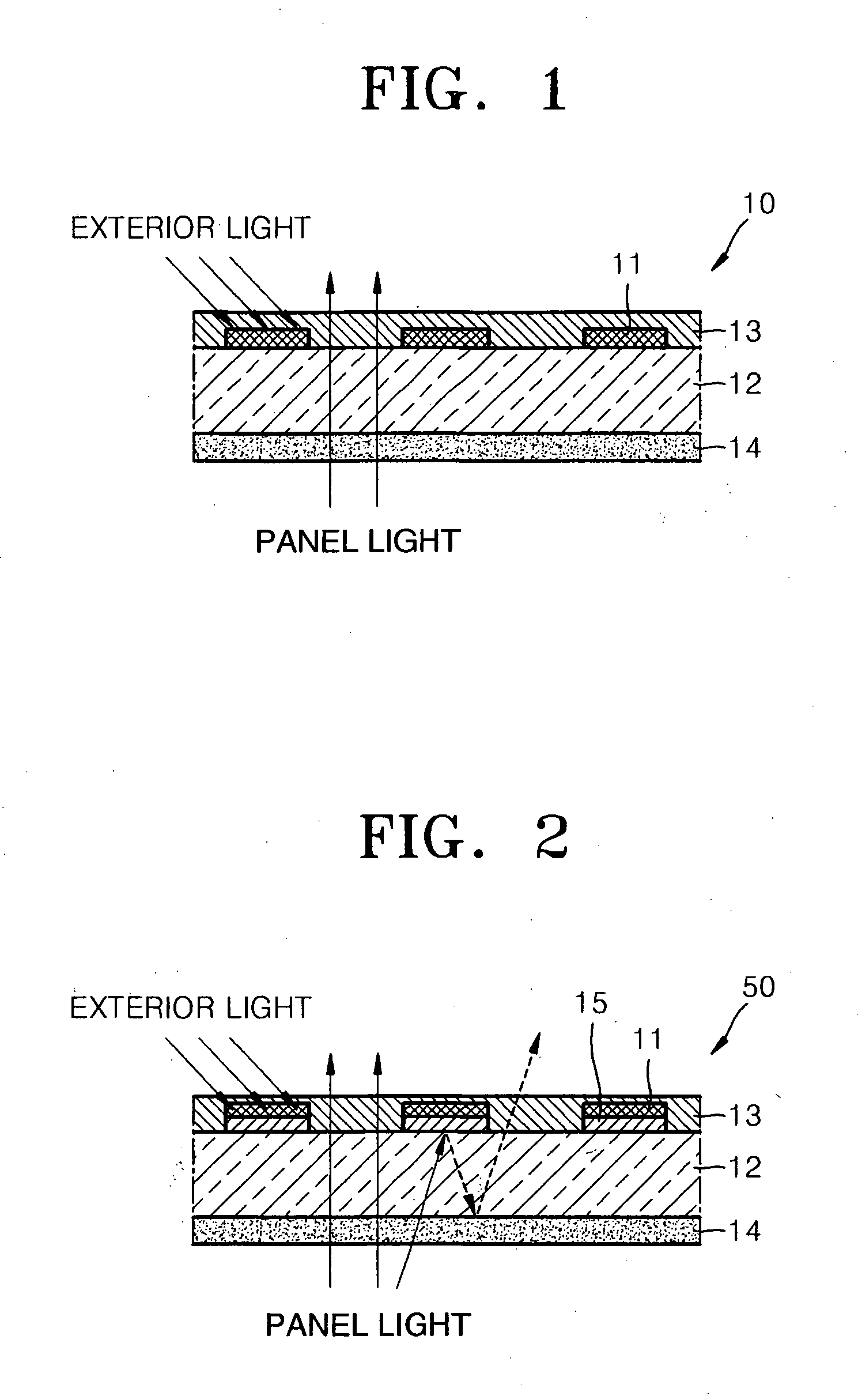
[0026]FIG. 1 is a cross-sectional view illustrating a configuration of a filter 10 according to an embodiment of the present invention.

[0027]Referring to FIG. 1, the filter 10 includes a plurality of light absorbing pattern units 11, a base film 12, a reflection prevention layer 13 and an adhesive layer 14.

[0028]The light abso...


PUM


Abstract

A filter that can prevent a double image and increase bright room contrast, has a reduced weight and low manufacturing cost, and is easy to manufacture, and a plasma display apparatus employing the filter. The filter includes a base film, a plurality of light absorbing pattern units that are extended on a surface of the base film in predetermined intervals having a stripe shape, blocking electromagnetic waves, and a reflection prevention layer covering the plurality of light absorbing pattern units.

Description

CLAIM OF PRIORITY[0001]This application makes reference to, incorporates the same herein, and claims all benefits accruing under 35 U.S.C. §119 from an application for FILTER AND DISPLAY APPARATUS HAVING THE SAME, earlier filed in the Korean Intellectual Property Office on May 30, 2007 and there duly assigned Serial No. 10-2007-0052926.BACKGROUND OF THE INVENTION[0002]1. Field of the Invention[0003]The present invention relates to a filter and a plasma display apparatus having the filter, and more particularly, to a filter that can increase bright room contrast by increasing transmittance of light emitted inside and blocking light incident from the outside, and can be made lightweight, slim and cost effective for a plasma display apparatus using the filter.[0004]2. Description of the Related Art[0005]Plasma display apparatuses that use a plasma display panel are flat panel display apparatuses that display an image using a gas discharge, and are expected to become one of the next gen...

Claims


Application Information

Patent Timeline
Patent Type & Authority Applications(United States)
IPC IPC(8): H01J5/16H01J61/40
CPCG02B5/201G02B5/22H01J11/10H01J11/44H01J2211/442H01J2211/444H01J2211/446G02B5/20
Inventor HWANG, CHA-WON
Owner SAMSUNG SDI CO LTD
Learn More