
Electrooptic device and electronic device

a technology of electronic devices and optical components, applied in the field of optical components and electronic components, can solve the problems of reducing the luminance of the image seen, blocking the light exiting from the image display surface, and affecting the image brightness, so as to prevent the depolarization of light

Inactive Publication Date: 2010-04-13
EPSON IMAGING DEVICES CORP +1
View PDF9 Cites 14 Cited by
  • Summary
  • Abstract
  • Description
  • Claims
  • Application Information

AI Technical Summary

Benefits of technology

"The invention relates to an electrooptic device that prevents depolarization of light in the device. Depolarization occurs when light passes through a lens and can cause issues with image quality. The invention solves this problem by using a polarizing-axis control unit that allows light with a first polarizing axis to pass through and changes part of the light into light with a second polarizing axis that is perpendicular to the first polarizing axis. A lens is then used that includes a plurality of linear lens patterns that direct the light with the first polarizing axis and the light with the second polarizing axis separated by the polarizing-axis control unit. This ensures that the polarizing axis of the light incident on the lens is parallel or perpendicular to the extension of the lens patterns, preventing depolarization and improving image quality. The invention can be applied to electrooptic devices such as display panels and stereoscopic displays."

Problems solved by technology

However, since the image display device disclosed in Japanese Patent No. 2857429 has the electronic parallax barrier on the image display surface on the viewer side, it has the disadvantage that part of the light that has exited from the image display surface is blocked by the light-shielding portions of the electronic parallax barrier.
This decreases the luminance of the image seen by the viewer, resulting in a dark image.
Accordingly, this display device has the problem of difficulty in providing high-definition images to viewers in different positions.
However, the image display device using the lenticular lens has the problem of depolarization in which the polarizing characteristic of the light incident on the lenticular lens is eliminated by the double refraction or the scattering of light.

Method used


Image

  • Electrooptic device and electronic device
  • Electrooptic device and electronic device
  • Electrooptic device and electronic device

Examples


first embodiment

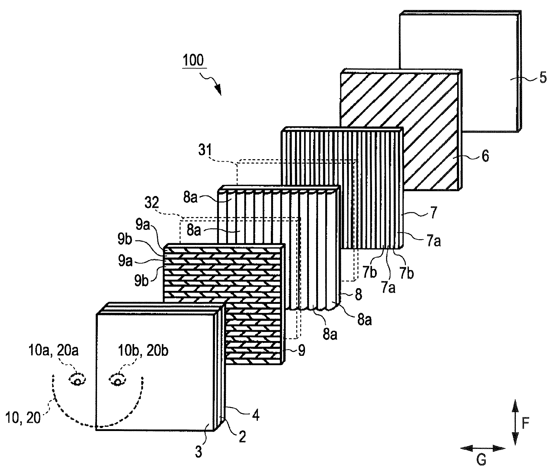
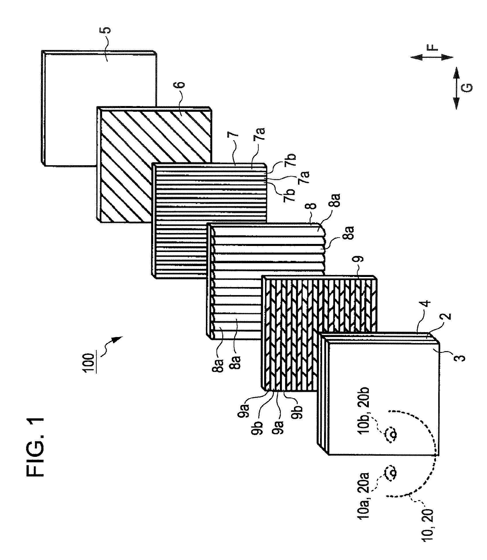
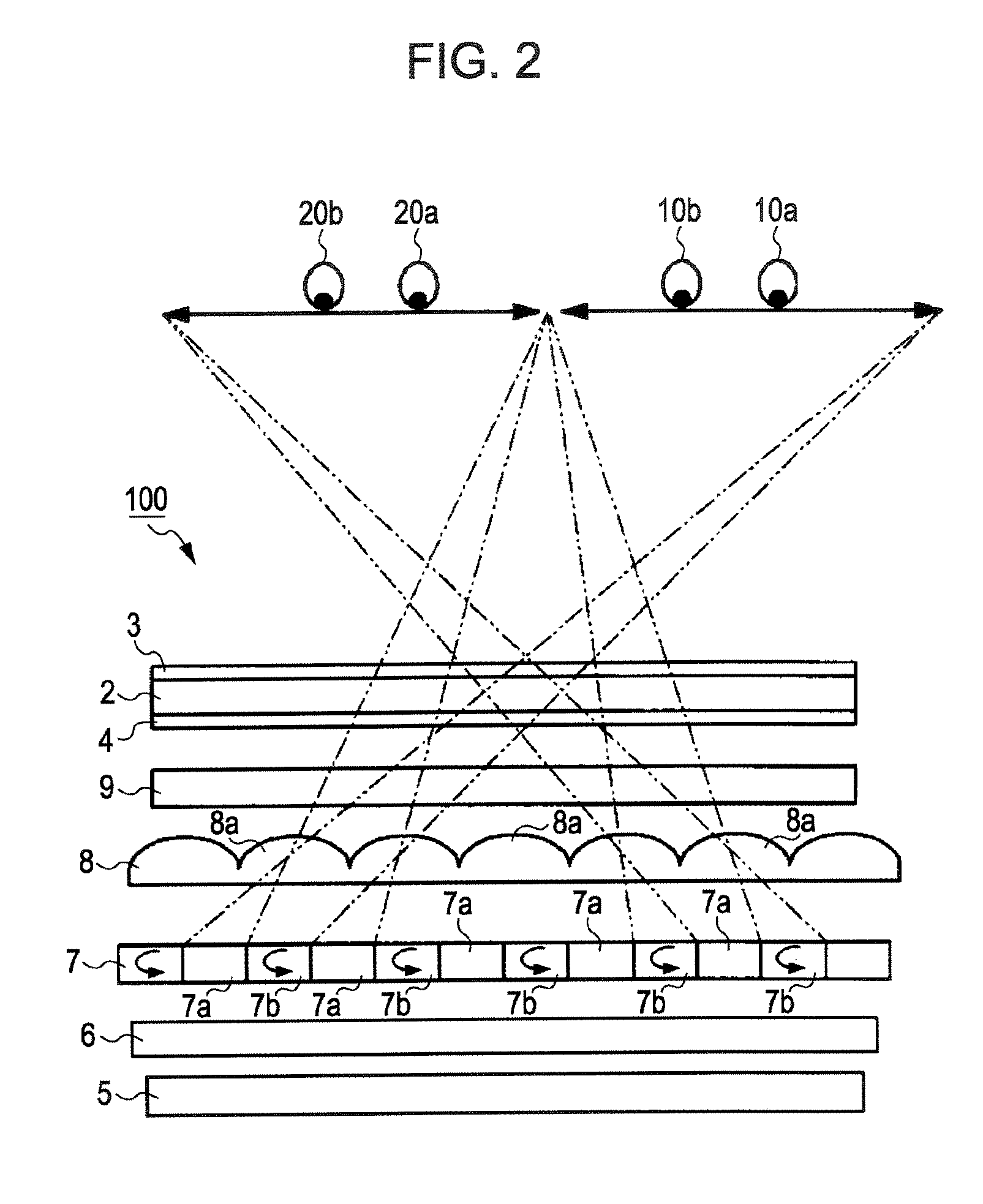
[0041]FIG. 1 is an exploded perspective view of an image display device 100 according to a first embodiment of the invention; FIG. 2 is a diagram for describing the principle of the image display device 100 according to the first embodiment of FIG. 1, in which viewers see the image display device 100 from above; FIG. 3 is a fragmentary enlarged view of the polarization-controlling liquid crystal panel of the image display device 100 according to the first embodiment; FIG. 4 is a diagram for describing the principle of the image display device 100 of FIG. 1, in which viewers see the image display device 100 from a side; FIG. 5 is an exploded perspective view of the image display device 100 according to the first embodiment for describing the principle thereof; and FIG. 6 is a cross-sectional view of the image display device 100 according to the first embodiment. Referring to FIGS. 1 to 6, the structure of the image display device 100 according to the first embodiment will be describe...

second embodiment

[0071]An image display device 100 according to a second embodiment of the invention will be described. FIG. 13 is an exploded perspective view of the image display device 100.

[0072]The image display device 100 according to the second embodiment has substantially the same structure and the same system of the double display mode and the stereoscopic display mode as those of the image display device 100 according to the first embodiment shown in FIGS. 1 to 10. As shown in FIG. 13, the image display device 100 according to the second embodiment is different from the image display device 100 of the first embodiment in that it includes a half-wave plate 31 between the polarizing plate 6 and the lenticular lens 8 and a half-wave plate 32 between the lenticular lens 8 and the polarizing plate 4, in other word, it includes the half-wave plates 31 and 32 on the light-incident side and the light-exiting side of the lenticular lens 8, respectively.

[0073]FIG. 14 shows the relationship between th...


PUM


Abstract

An electrooptic device includes: a display panel for displaying images; an illumination system for applying light to the display panel; a polarizing-axis control unit disposed between the illuminating system and the display panel, the control unit allowing light having a first polarizing axis of the light emitted from the illuminating system to pass through, and changing part of the light from the illuminating system into light with a second polarizing axis that is substantially orthogonal to the first polarizing axis; a lens disposed between the polarizing-axis control unit and the display panel, the lens including a plurality of linear lens patterns directing the light with the first polarizing axis and the light with the second polarizing axis separated by the polarizing-axis control unit into specified directions; a first polarizing unit disposed between the illumination system and the lens; and a second polarizing unit disposed between the display panel and the lens. Both the polarizing axis of the first polarizing unit and the polarizing axis of the second polarizing unit are substantially parallel to or perpendicular to the extension of the lens patterns.

Description

BACKGROUND[0001]1. Technical Field[0002]The present invention relates to an electrooptic device and an electronic device suitable for use in displaying various information.[0003]2. Related Art[0004]Known electrooptic devices include image display devices such as stereoscopic display devices that display 3D images and double display devices that present different images to viewers in different positions. One of the 3D stereoscopic display devices is disclosed in Japanese Patent No. 2857429 which is capable of stereoscopic display of a parallax barrier system. This image display device controls an electronic parallax barrier of the image display surface adjacent to the viewer by a control means such as a microcomputer to generate stripe openings and light shielding portions of a specified shape in positions of the electronic parallax barrier. For example, the openings of the electronic parallax barrier are formed so that when 3D images are presented to the viewer, an image for left ey...

Claims


Application Information

Patent Timeline
Patent Type & Authority Patents(United States)
IPC IPC(8): G02B27/26G02B27/22G02B30/25G02B30/27
CPCG02B27/2214G02F1/133528G02F1/133526H04N13/32G02B30/27
Inventor SUGIYAMA, NOBUO
Owner EPSON IMAGING DEVICES CORP
Learn More