An assembled energy-saving anode steel claw for an aluminum electrolytic cell and its assembly method

A technology of aluminum electrolytic cell and anode steel claw, which is applied to the field of assembled energy-saving anode steel claw of aluminum electrolytic cell and its assembly, can solve the problems of depolarization, large pressure drop of steel claw, large resistance, etc.

Active Publication Date: 2020-10-27
NORTHEASTERN UNIV ENG & RES INST CO LTD
View PDF11 Cites 0 Cited by
  • Summary
  • Abstract
  • Description
  • Claims
  • Application Information

AI Technical Summary

Problems solved by technology

In the traditional method, the steel claws are cast steel parts with high resistance. In the production of the electrolytic cell, the pressure drop of the steel claws is large, the electric power decreases, and the production cost increases; in the traditional method, the steel claws and the guide rods are separated by explosion The solder block is connected, and the welding seam of the explosive solder block is very easy to crack and depolarization occurs

Method used


Image

  • An assembled energy-saving anode steel claw for an aluminum electrolytic cell and its assembly method
  • An assembled energy-saving anode steel claw for an aluminum electrolytic cell and its assembly method
  • An assembled energy-saving anode steel claw for an aluminum electrolytic cell and its assembly method

Examples


Embodiment 1

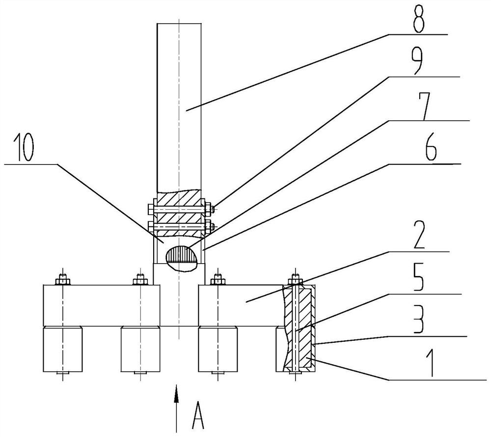
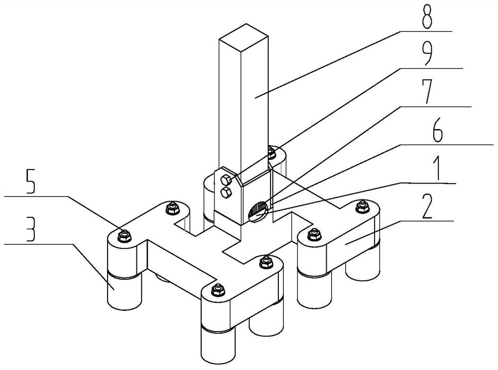
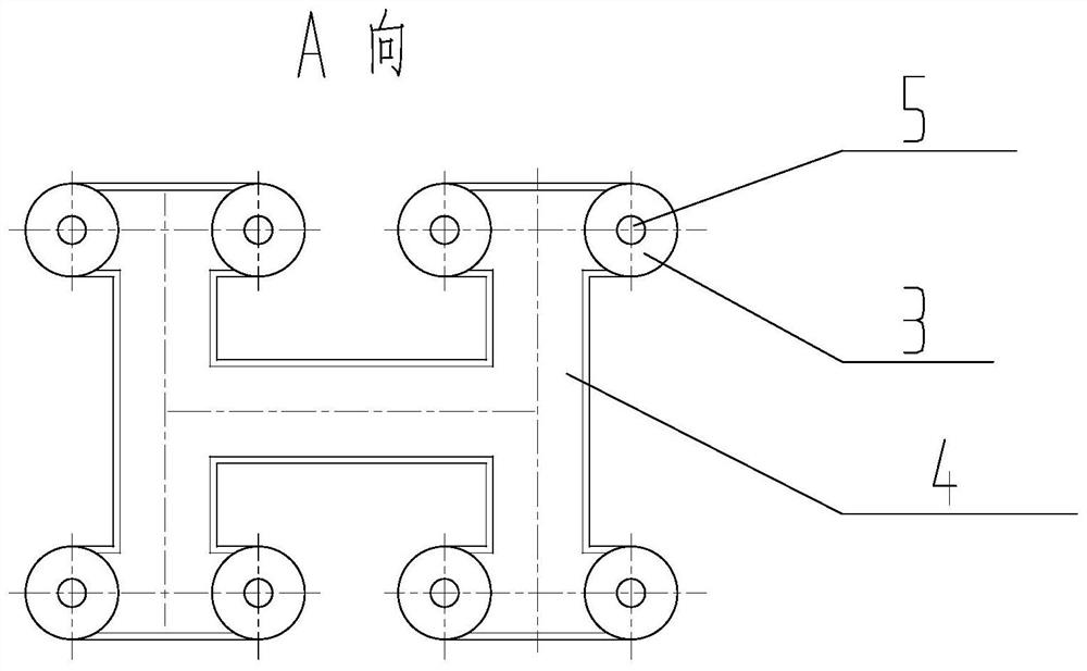
[0030] Aluminum electrolytic cell assembled energy-saving anode steel claw structure such as figure 1 As shown, the axonometric drawing is shown as figure 2 As shown, the A-direction structure is as follows image 3 As shown, it includes claw core, shell and protective sleeve. The claw core is composed of upper main rod, middle cross bar and multiple bottom support rods. The lower end of an upper general rod is connected with the middle part of a first-level cross bar. The two ends of each are respectively connected to the middle of a second-level crossbar, and each end of the second-level crossbar is provided with a bottom strut, and there are 8 bottom struts in total;

[0031] The outside of the upper main bar of the claw core, the top surface of the middle cross bar and the side of the middle cross bar are covered with a shell, and each bottom support is respectively covered with a protective sleeve; the bottom surface of the middle cross bar of the claw core is covered w...

Embodiment 2

[0042] Aluminum electrolytic cell assembled energy-saving anode steel claw structure such as Figure 4 As shown, the axonometric drawing is shown as Figure 5 As shown, the A-direction structure is as follows Figure 6 As shown, the bottom end of the upper main bar of the claw core is connected with the middle part of the cross bar, and four bottom struts are evenly distributed below the cross bar, and the rest are the same as in Embodiment 1.


PUM


Abstract

The invention discloses an aluminum electrolysis cell assembly type energy-saving anode steel claw and an assembling method of the aluminum electrolysis cell assembly type energy-saving anode steel claw. The steel claw comprises a claw core, the outer side of an upper portion main rod and the top and side faces of a middle transverse rod of the claw core are sleeved with a shell, branch rods are sleeved with protection casing pipes, the bottom face is covered with a lower protection plate, the shell and the protection casing pipes are fixed to the claw core through branch rod bolts, and the claw core is made from metal aluminum. The assembling method comprises the steps that 1, the claw core, the shell, the lower protection plate and the protection casing pipes are manufactured; and the claw core, the shell and the protection casing pipes are drilled; 2, the claw core is sleeved with the shell, the bottom of the claw core is covered with the lower protection plate, and the bottom branch rods are sleeved with the protection casing pipes and fixed through the branch rod bolts; 3, an aluminum plate is welded between an aluminum guide rod and the claw core; 4, a connection steel plateis welded to the top end of the shell; and 5, the connection steel plate and the aluminum guide rod are fixed through guide rod bolts. By means of the steel claw structure, multiple defects of a steelclaw adopted in traditional electrolysis production can be overcome.

Description

technical field [0001] The invention belongs to the technical field of aluminum electrolysis equipment, and in particular relates to an assembled energy-saving anode steel claw of an aluminum electrolysis cell and an assembly method thereof. Background technique [0002] The anode steel claw of the electrolytic cell is an important part of the anode group on the electrolytic cell, which is mainly used for conducting electricity and bearing the load of the anode carbon block. In the traditional method, the steel claws are cast steel parts with high resistance. In the production of the electrolytic cell, the pressure drop of the steel claws is large, the electric power decreases, and the production cost increases; in the traditional method, the steel claws and the guide rods are separated by explosion When the solder block is connected, the welding seam of the explosive solder block is very easy to crack and depolarization occurs. Contents of the invention [0003] The purp...

Claims


Application Information

Patent Timeline
Patent Type & Authority Patents(China)
IPC IPC(8): C25C3/12
CPCC25C3/125
Inventor 关永军班允刚刘靖董慧李扬刘彻朱昌宁
Owner NORTHEASTERN UNIV ENG & RES INST CO LTD
Why Eureka
Try Eureka