Side face underload weld joint cargo boom
A technology of light load and boom, which is applied in the direction of cranes, etc., can solve the problems of not reducing the strength of the boom, affecting the strength of the boom, reducing the weight of the boom, etc., so that it is not easy to open welding, save materials, avoid The effect of welding
- Summary
- Abstract
- Description
- Claims
- Application Information
AI Technical Summary
Problems solved by technology
Method used
Image
Examples
Embodiment 1
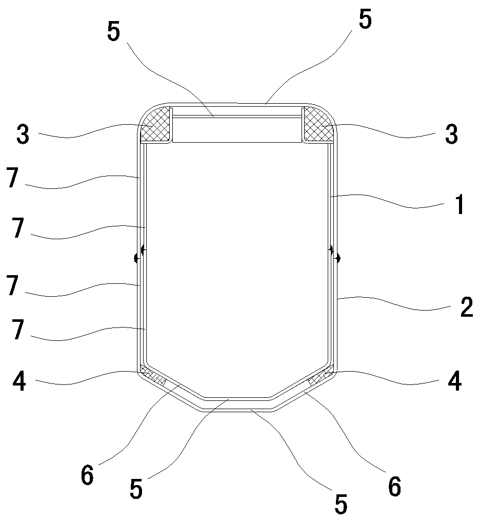
[0011] Embodiment one, such as figure 1 As shown, it includes an inner arm 1 and an outer arm 2. The inner arm 1 is set in the outer arm 2 along the extending direction of the hollow cavity of the outer arm 2. The two upper corner positions of the rear end of the inner arm 1 are respectively provided with The upper sliding wear-resistant block 3 that is slidably matched to the two inner corner positions on the upper side of the arm 2, and the lower sliding wear-resistant block 4 that is slidably fitted to the lower outer wall of the inner arm 1 on the lower inner wall of the front end of the outer arm 2 , the inner arm 1 and the outer arm 2 are respectively composed of two parts, the upper arm body and the lower arm body folded into a groove shape. The butt edge positions of the left and right sides are welded together as a whole.
[0012] The positions of the welds on the same side of the inner arm 1 and the outer arm 2 are staggered up and down without interfering with each...
Embodiment 2
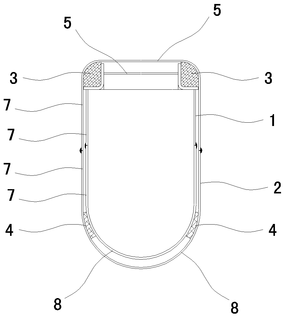
[0016] Embodiment two, such as figure 2 As shown, the difference from Embodiment 1 is that the middle position of the upper arm body of the inner arm 1 and the outer arm 2 is a plane 5 extending along the direction of the cavity of the inner arm 1, and the two sides of the plane 5 are folded downward to form a 90-degree circle. Arc-shaped, the lower sides of two 90-degree circular arcs are parallel and extend downwards to form the left and right facades 7 of the upper arm body. The lower sides of the lower arm bodies of the inner arm 1 and the outer arm 2 are axially along the inner arm 1. A 180-degree arc-shaped surface 8 extending along the direction of the cavity. The edges on both sides of the 180-degree arc-shaped surface 8 extend upwards in parallel to form two left and right facades 7 of the lower arm body. The inner arm 1 and the outer The lower sides of the two facades 7 of the upper arm body of the arm 2 are welded to the upper sides of the two facades 7 of the lowe...
Embodiment 3
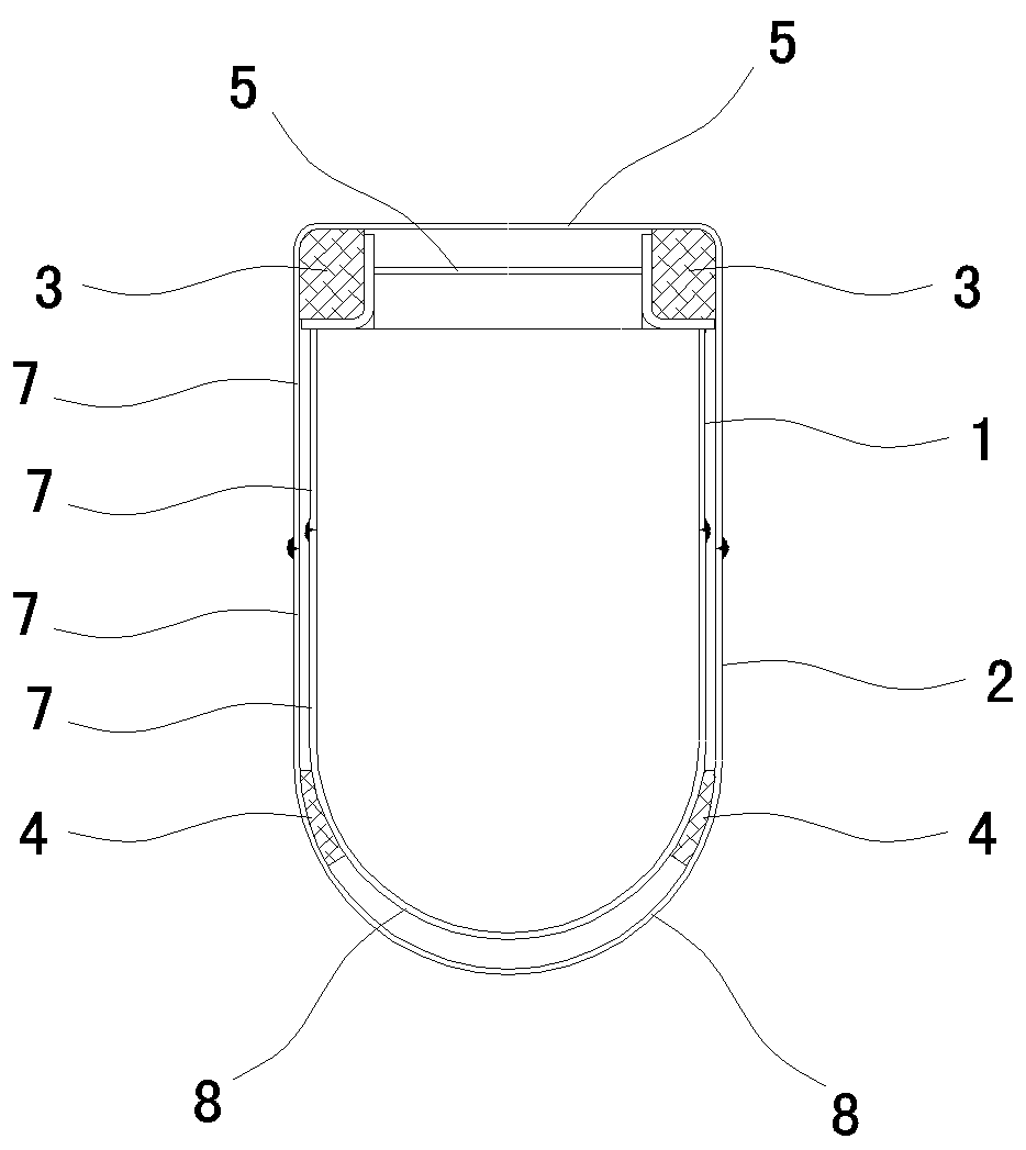
[0017] Embodiment three, such as image 3 As shown, the difference from Embodiment 1 is that the middle position of the upper arm bodies of the inner arm 1 and the outer arm 2 is a plane 5 extending along the direction of the cavity of the inner arm 1, and the two sides of the plane 5 are folded downwards to form a right angle. , the lower sides of the two right angles are parallel and extend downwards to form the left and right facades 7 of the upper arm body. The extended 180-degree arc-shaped surface 8, the edges on both sides of the 180-degree arc-shaped surface 8 extend upwards in parallel to form the left and right facades 7 of the lower arm body, and the upper arm body of the inner arm 1 and the outer arm 2 The lower sides of the two facades 7 are welded to the upper sides of the two facades 7 of the lower arms of the inner arm 1 and the outer arm 2 respectively, and each upper sliding wear-resistant block 3 is connected to the two inner corners on the upper side of the...
PUM
 Abstract
Description
Claims
Application Information
 - R&D
- Intellectual Property
- Life Sciences
- Materials
- Tech Scout
- Unparalleled Data Quality
- Higher Quality Content
- 60% Fewer Hallucinations
Browse by: Latest US Patents, China's latest patents, Technical Efficacy Thesaurus, Application Domain, Technology Topic, Popular Technical Reports.
© 2025 PatSnap. All rights reserved.Legal|Privacy policy|Modern Slavery Act Transparency Statement|Sitemap|About US| Contact US: help@patsnap.com


