
A h-type top-coal caving support pressure plate fixing mechanism

A fixing mechanism and top-coal caving technology, which is applied in mine roof support, mining equipment, earthwork drilling and mining, etc., can solve problems such as insufficient strength, corrosion of welding joints, and falling off of fixing blocks, so as to improve the compressive capacity and prevent moisture Corrosion, increase the effect of bearing capacity

Active Publication Date: 2022-03-25
LIUPANSHUI NORMAL UNIV
View PDF6 Cites 0 Cited by
  • Summary
  • Abstract
  • Description
  • Claims
  • Application Information

AI Technical Summary

Problems solved by technology

The column is mainly based on the fixed block as the fulcrum, and the bracket pressure plate and the fixed pin are mainly used to crush the arc socket of the column on the column. Since the fixed block of the fixed column and the base of the bracket are welded on a plane, it is easy to cause the welding place of the fixed column fixed block after a long time. Stress fatigue, resulting in open welding, unable to move or lift the frame
[0004] The current H-type top-coal caving support, the fixed block is simply welded on the plane, the strength is not enough, and the overload operation causes the fixed block of the support column and the support plate to open welding. In this humid underground environment, some corrosive elements will be contained, so the moisture Will corrode the weld
A variety of reasons cause the fixed block to fall off or be lost, and the support plate loses its fulcrum, causing the column to be unable to effectively lift the base to move the support, which brings inconvenience to the team's normal advancement of the working surface, increases the labor intensity of the team's workers, and seriously affects the output.

Method used


Image

  • A h-type top-coal caving support pressure plate fixing mechanism
  • A h-type top-coal caving support pressure plate fixing mechanism
  • A h-type top-coal caving support pressure plate fixing mechanism

Examples


Embodiment Construction

[0025] The following will clearly and completely describe the technical solutions in the embodiments of the present invention with reference to the accompanying drawings in the embodiments of the present invention. Obviously, the described embodiments are only some, not all, embodiments of the present invention. The specific embodiments described here are only used to explain the present invention, not to limit the present invention. Based on the embodiments of the present invention, all other embodiments obtained by persons of ordinary skill in the art without making creative efforts belong to the protection scope of the present invention.

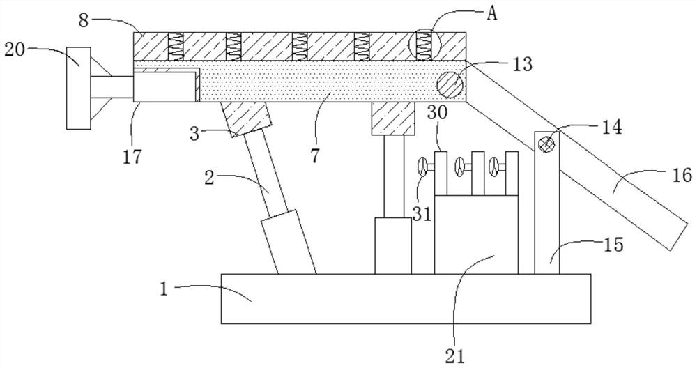
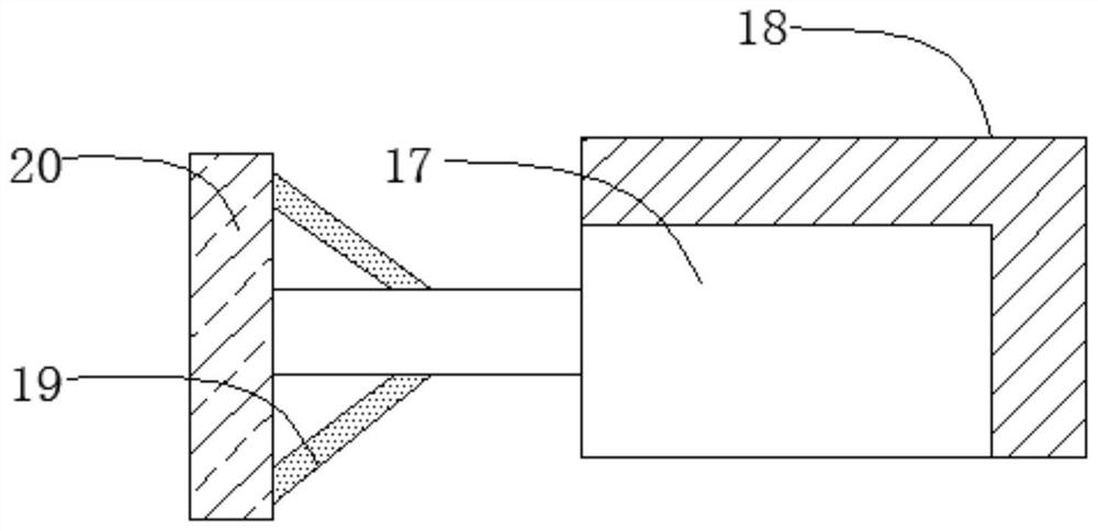
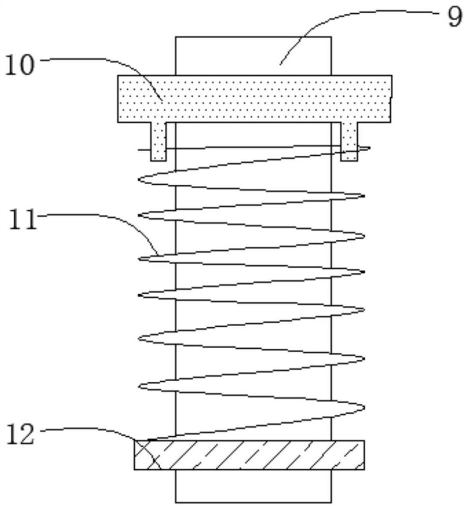
[0026] The present invention provides such as Figure 1-5 The shown H-type top-coal caving support pressure plate fixing mechanism includes a base 1 for supporting the entire top-coal caving support, and a first hydraulic cylinder 2 is installed on the top surface of the base 1 to provide power for supporting the top beam 7 , the outside...


PUM


Abstract

The invention discloses an H-type top-coal caving support pressure plate fixing mechanism, which belongs to the technical field of top-coal caving hydraulic supports, and includes a base, a first hydraulic cylinder is installed on the top surface of the base, and an output end of the first hydraulic cylinder A fixed block is welded, the top surface of the fixed block is welded with a top beam, the two sides of the fixed block are respectively welded with connection blocks, and the two groups of connection blocks are respectively connected to the bottom side of the top beam by bolts, and the top beam A pressure-resistant layer is welded on the top surface, a support is welded at one end of the top beam, a second hydraulic cylinder is welded at one side of the L-shaped support, and a support pressing plate is welded at the output end of the second hydraulic cylinder. The invention has simple structure and high practicability, can enhance the load-bearing capacity of the fixed block and the bracket pressing plate, reduce the risk of welding, not only can increase the compressive capacity of the whole bracket, improve the service life of the bracket, but also can dry the bracket through the drying box. The welded joints are dried to prevent corrosion by moisture.

Description

technical field [0001] The invention belongs to the technical field of top coal caving hydraulic supports, and in particular relates to an H-type top coal caving support pressure plate fixing mechanism. Background technique [0002] The top-coal caving hydraulic support is developed on the basis of the common longwall working face hydraulic support. It has the same functions in controlling the basic items, maintaining the direct top, self-moving and pushing conveyors, but the top-coal caving mechanism and the support are affected by The functions of power, head support, dust reduction and other aspects are different. The top coal caving hydraulic support is stable, the coal opening is continuous, the back loss is small, and the coal caving effect is good. For thick coal seam mining, the equipment investment is small and the cost performance is high. It is suitable for thick coal seams with coal seams below medium hardness, with obvious or well-developed joints and fissures. ...

Claims


Application Information

Patent Timeline
Patent Type & Authority Patents(China)
IPC IPC(8): E21D23/00E21D23/04E21D23/16E21F3/00
CPCE21D23/0013E21D23/04E21D23/16E21F3/00
Inventor 梁华杰彭大江王加双
Owner LIUPANSHUI NORMAL UNIV
Learn More