Graphical user interface including zoom control box representing image and magnification of displayed image

Inactive Publication Date: 2010-04-13
CEDAR LANE TECH INC
View PDF40 Cites 56 Cited by
  • Summary
  • Abstract
  • Description
  • Claims
  • Application Information

AI Technical Summary

Benefits of technology

[0012]In yet another aspect of the present invention, a method of controlling magnification of and portion of an original image displayed within an image display window includes the steps of displaying a zoom control box including an inner region positioned within an outer region, wherein a size of the inner region relative to the outer region represents the magnification of the original image being displayed within the image display window and further wherein a position of the inner region within the outer region represents the portion of the original image being displayed within the image display window and changing the size and position of the inner region in response to input commands. The size of the inner region is decreased when an input command is entered selecting the inner region. The size of the inner region is increased when an input command is entered selecting the outer region. The input commands are entered using a cursor control device and the inner and outer regions are selected by positioning a cursor within an appropriate region and clicking the cursor control device. The method further includes the step of displaying the portion of the original image within the image display window. The steps of displaying are all preferably completed on a display of a computer system, wherein the computer system includes the display, a memory and an input device. The input device is preferably a mouse. The method further includes the step of displaying a magnification factor within the inner region numerically representing the magnification of the original image being displayed within the image display window. The method further includes the step of receiving the original image from an image source. The original image is a s

Problems solved by technology

There is currently a lack of image display devices which allow easy control of display parameters

Method used


Image

  • Graphical user interface including zoom control box representing image and magnification of displayed image
  • Graphical user interface including zoom control box representing image and magnification of displayed image
  • Graphical user interface including zoom control box representing image and magnification of displayed image

Examples


Embodiment Construction

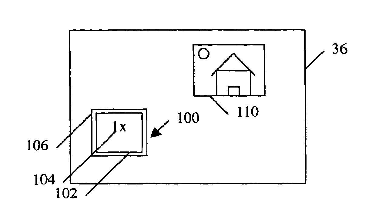
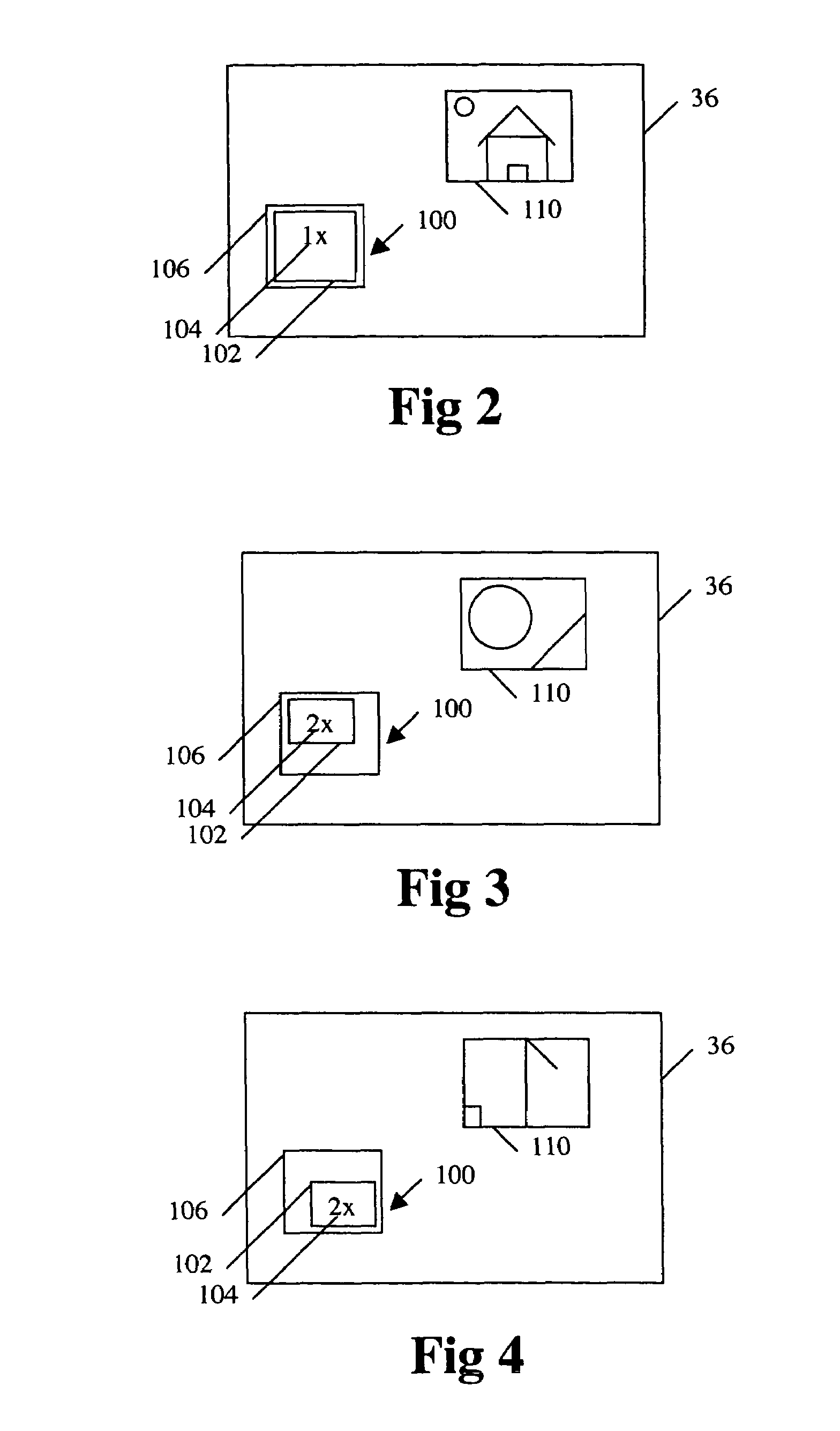
[0018]A graphical user interface (GUI) graphically corresponds to an image display window 110 through which a single image or a stream of images or video frames are displayed. The GUI and the image display window 110 are displayed on a display device such as a display device 36 of a computer system 20, illustrated in FIG. 1. Alternatively, the GUI and the image display window 110 are displayed on and controlled by any one or more appropriate devices. The GUI includes a zoom control box 100 having an inner region 102 positioned within an outer region 106.

[0019]A user controls aspects and changes parameters of the image displayed within the image display window 110 using a cursor control device 50, such as a keyboard 38 or mouse 40, of the computer system 20 illustrated in FIG. 1 to enter input commands within the zoom control box 100 by selecting appropriate regions of the zoom control box 100. The cursor control device can be a mouse, keypad, trackball, touch pad, remote control or ...


PUM


Abstract

A graphical user interface (GUI) graphically corresponds to an image display window through which a single image or a stream of images or video frames are displayed. The GUI includes a zoom control box having an inner region positioned within an outer region. The size of the inner region relative to the outer region represents the magnification of the portion of the image being displayed within the image display window. The magnification of the image being displayed is increased by using a cursor control device to position a cursor within the inner region and clicking the cursor control device. The magnification of the image being displayed is decreased by using the cursor control device to position the cursor outside of the inner region but inside of the outer region and clicking the cursor control device. As the magnification is increased or decreased, the size of the inner region relative to the outer region is changed accordingly. A magnification factor is also displayed within the inner region to display a numeric representation of the current magnification. The position of the inner region within the outer region represents the portion of the entire image being displayed within the image display window. The portion of the image being displayed within the image display window is changed by clicking and dragging the inner region to the desired position within the outer region using the cursor control device.

Description

RELATED APPLICATIONS[0001]This application is a divisional application based on prior application Ser. No. 09 / 433,978, filed on Nov. 4, 1999, now U.S. Pat. No. 6,803,391.FIELD OF THE INVENTION[0002]The present invention relates to the field of computers and image display devices having graphically-oriented user interfaces. More particularly, the present invention relates to the field of computers and image display devices having graphically-oriented user interfaces through which the display of an image is graphically controlled.BACKGROUND OF THE INVENTION[0003]Image display devices are used to display both still images and moving video images, which are generated by or stored locally within the image display device or received from an external source device. A still or video frame image will herein be referred to collectively as an image. Typically, the image display device displays the image or series of images within an image display window, which takes up either all or a portion ...

Claims


Application Information

Patent Timeline
IPC IPC(8): G06F3/048G09G5/00
CPCG06F3/0481G06F2203/04806
Inventor ROMAN, KENDYL A.RAPOSO, R. PAUL
Owner CEDAR LANE TECH INC
Why Eureka
Try Eureka