Retractable step for cab of mobile machine

a mobile machine and step technology, applied in the direction of roofs, transportation and packaging, vehicle arrangements, etc., can solve the problems of affecting the rotation and/or tilting of the cab, the adder is bulky, etc., and achieves the effect of convenient and safe access and easy and safe access

Active Publication Date: 2010-04-20
TIMBERPRO
View PDF74 Cites 21 Cited by
  • Summary
  • Abstract
  • Description
  • Claims
  • Application Information

AI Technical Summary

Benefits of technology

[0004]The present invention solves this need and other problems in the field of cabs for material handling machines by providing, in a preferred form, a retractable step assembly having a step that can be moved from a retracted position not interfering with operation of the mobile machine to an extended position allowing easy and safe access to and from a cab. In the preferred form, the cab includes a platform and a plurality of partitions mounted on a top side of the platform to define an enclosure for receiving an operator. A door is provided in one of the partitions to allow access to and from the enclosure. The step assembly includes a leg slideably received in a through-hole extending between the top side and an underside of the platform. A step is mounted to a lower end of the leg that extends downward through the through-hole of the platform. An upper end of the leg is fixed to a lower end of a spring whose upper end is fixed and spaced from the through-hole of the platform. The leg is movable between a retracted position and an extended position and biased by the spring from the extended position to the retracted position in which a spacing between the step and the underside of the platform is larger than that in the retracted position. The step can be stepped on by the operator to move the leg from the retracted position to the extended position where the leg is automatically latched against movement by the bias of the spring, thereby allowing easy and safe access to and from the enclosure. When the operator is in the enclosure, the leg in the extended position can be unlatched by the operator to move back to the retracted position under action of the spring such that the step will not interfere with operation of the machine.
[0005]A corner partition extends at an obtuse angle with the front partition and at an obtuse angle with the side partition including the door to enhance operator visibility and comfort and to minimize detrimental engagement of tree limbs during operation while providing a uniquely aesthetic appearance. A tube is mounted in an interconnection between the side partition and the corner partition and includes a vertical hole for receiving the spring and the leg. The upper end of the spring is in the form of a hook engaged with a pin extending through the upper end of the tube to allow simple assembly. A bottom plate is fixed to the underside of the platform and includes a slot through which the leg slideably extends. The leg and the slot of the bottom plate include non-circular cross-sections preventing rotation of the leg relative to the bottom plate. To prevent excessive extension of the leg out of the cab, a bulge is formed between the upper and lower ends of the leg and has a size greater than and abutting with the slot of the mounting plate. A shoe is mounted to the step and includes two spaced wings between which the step is securely received. Each wing has a plurality of serrations on a top edge thereof to avoid the operator from slipping and falling while stepping on the step. A latch retains the spring in a stretched state for releasably latching the leg in the extended position. The latch includes a handle and a plunger having a first end interconnected to the handle and a second end that engages with a catch portion of the leg when the leg is in the extended position. The handle can be pulled by the operator to disengage the second end of the plunger from the catch portion of the leg allowing the leg to move from the extended position to the retracted position. The step is, thus, retracted to avoid tree limbs, etc. from catching on it while the mobile machine is operating or moving in a row of trees.

Problems solved by technology

However, such ladders are bulky, tree limbs or the like easily catch on ladders when the machines are operating or moving in a row of trees, and such ladders could interfere with rotation and / or tilting of the cab during operation of the material handling machine.

Method used


Image

  • Retractable step for cab of mobile machine
  • Retractable step for cab of mobile machine
  • Retractable step for cab of mobile machine

Examples


Embodiment Construction

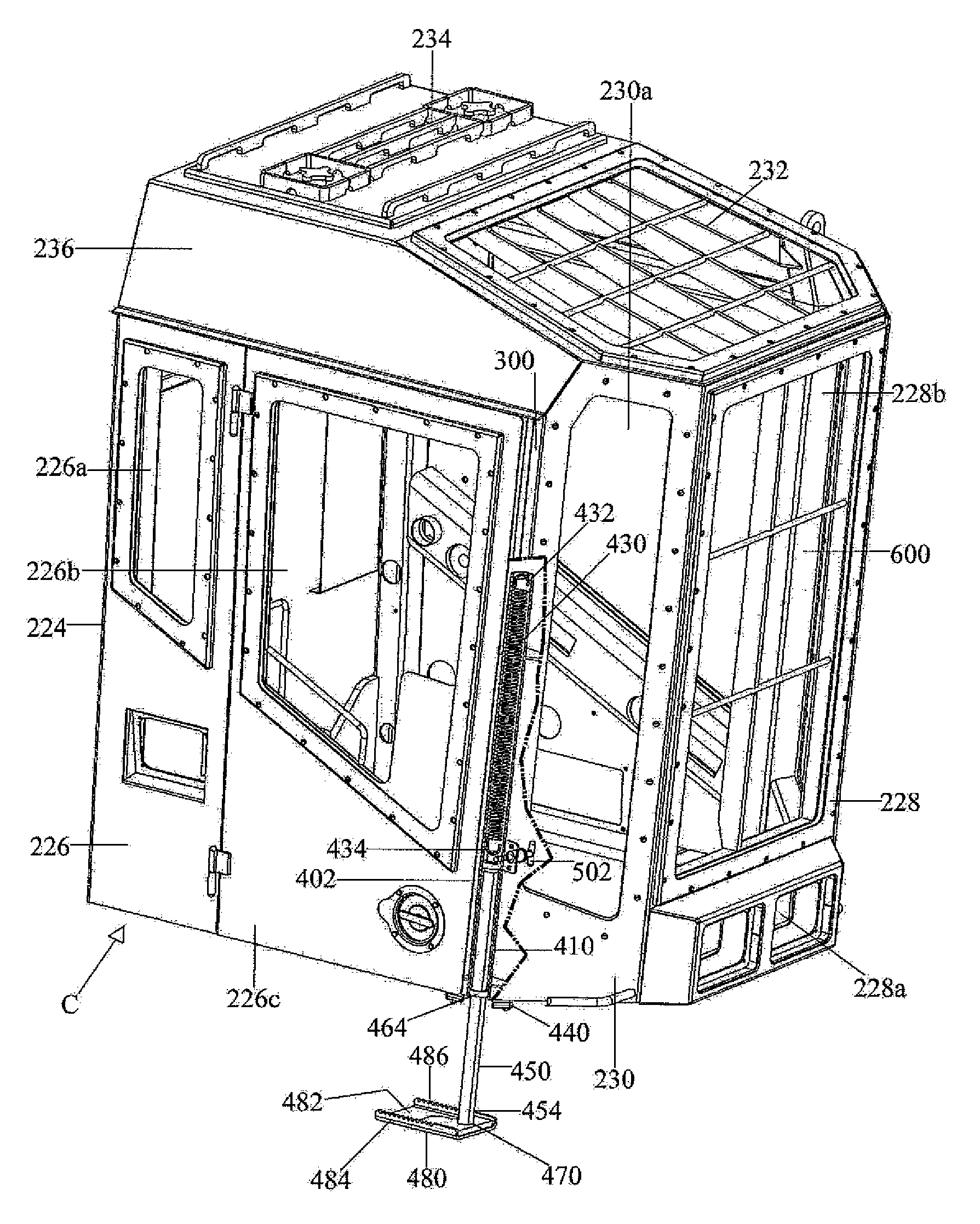
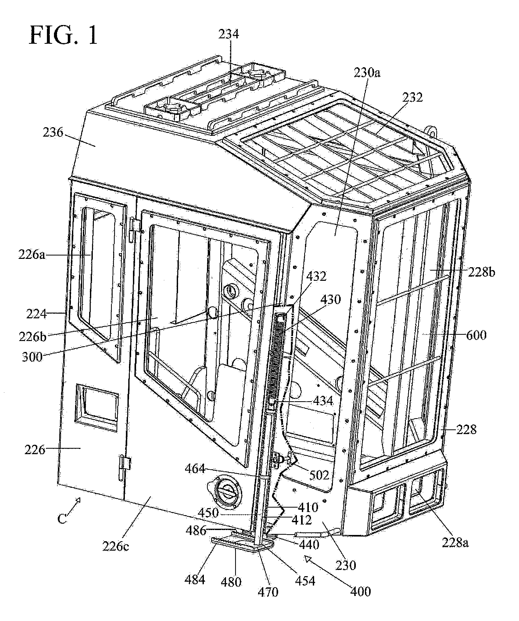
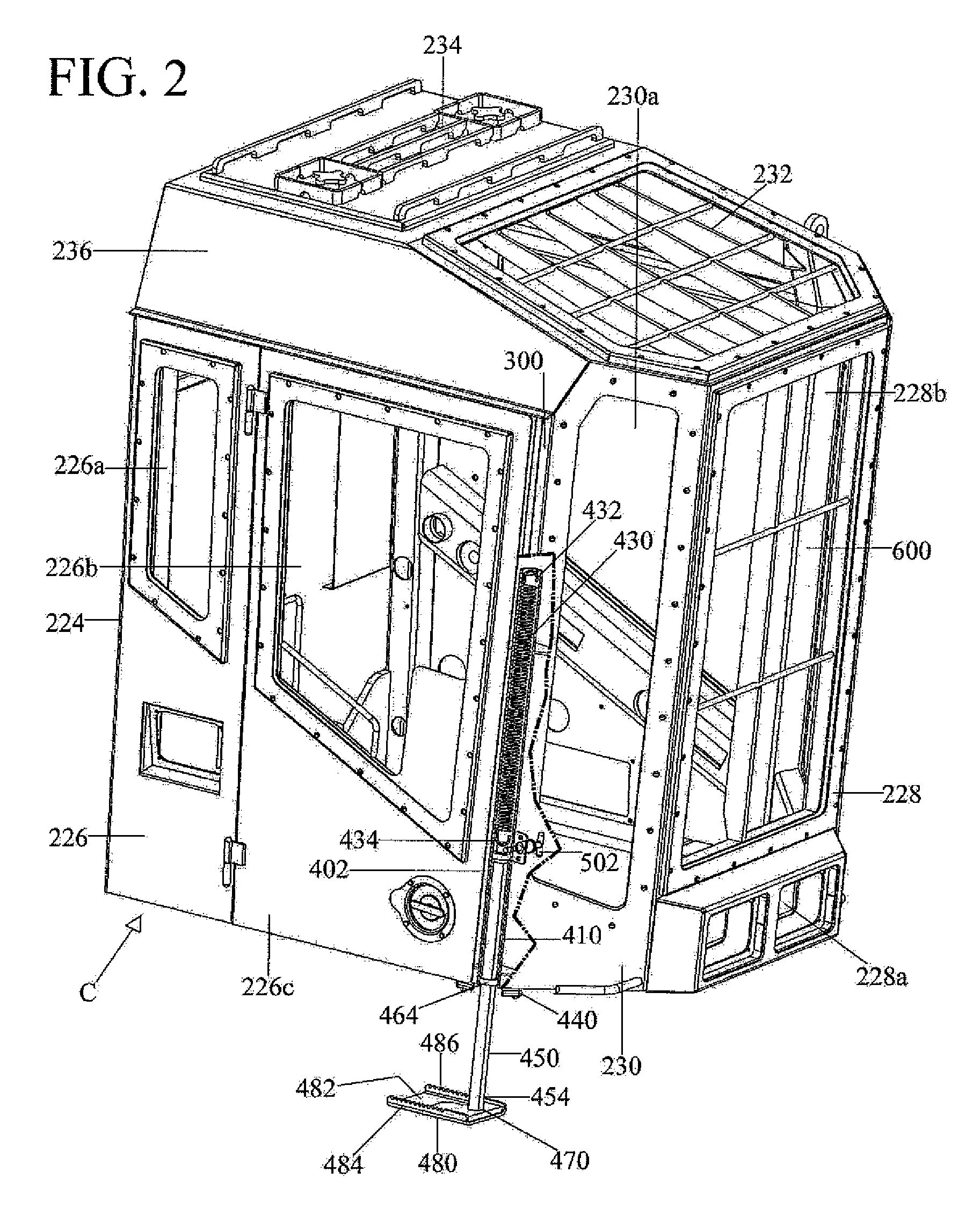
[0013]A retractable step assembly according to the preferred teachings of the present invention is shown in the drawings and generally designated 400. In a most preferred form, the retractable step assembly 400 is mounted to a cab C that can be mounted on a frame of a mobile machine including but not limited to a material handling machine such as a mobile tree handling machine. In the most preferred embodiment of the present invention shown, cab C is of the type shown and described in the U.S. patent application Ser. No. 11 / 306,434. For purpose of explanation of the basics teachings of the present invention, the same numerals designate the same or similar parts in the present figures and the figures of U.S. patent application Ser. No. 11 / 306,434. The description of the common numerals and cab C may be found herein and in U.S. patent application Ser. No. 11 / 306,434, which is hereby incorporated herein by reference.

[0014]It is however appreciated that cab C of other forms would be wit...


PUM


Abstract

A retractable step assembly (400) for a cab (C) for a mobile machine includes a leg (450) slideably received in a through-hole (408) in a platform (58) of a cab (C). An upper end (452) of the leg (450) is fixed to a lower end (434) of a stretchable spring (430) whose upper end (432) is fixed. A step (470) is mounted to the lower end (454) of the leg (450). The leg (450) is movable between a retracted position and an extended position in which the step (470) is nearer to the ground than in the retracted position. The step (470) can be stepped on by an operator to move the leg (450) to the extended position to thereby allow the operator to exit the cab (C) by stepping on the step (470). The leg (450) can be unlatched by the operator in the cab (C) to return to the retracted position under action of the spring (430).

Description

BACKGROUND OF THE INVENTION[0001]The present invention relates to a step for a cab of a machine and, more particularly, to a retractable step allowing easy and safe access to and from a cab of a material handling machine.[0002]Mobile machines such as material handling machines generally include a cab for receiving an operator. The cabs of some mobile machines, particularly tree handling machines, are located at a high level to provide clearance for the mobility providing members such as tires or tracks as well as the mechanisms such as turntable, tilt mechanisms, engines and the like. It would be desirable to include a ladder to allow easy access to and from the cab and to avoid injury to the operator resulting from falling while trying to access to or from the cab. However, such ladders are bulky, tree limbs or the like easily catch on ladders when the machines are operating or moving in a row of trees, and such ladders could interfere with rotation and / or tilting of the cab during...

Claims


Application Information

Patent Timeline
Patent Type & Authority Patents(United States)
IPC IPC(8): B60R3/02
CPCB60R3/02
Inventor CRAWFORD, PATRICK LEE
Owner TIMBERPRO
Why Eureka
Try Eureka