Cleaning device with squirter

a cleaning device and squirter technology, applied in the direction of floor cleaners, carpet cleaners, brushes, etc., can solve the problems of detergent or wax adhesion to the mop section and difficulty in removal

Inactive Publication Date: 2010-04-20
UNI CHARM CORP
View PDF10 Cites 40 Cited by
  • Summary
  • Abstract
  • Description
  • Claims
  • Application Information

AI Technical Summary

Benefits of technology

[0010]The present invention has been developed to solve the problems in the prior art set forth above and has an object to provide a cleaning device in which liquid dripping from a nozzle of a liquid jetting part or splattered around the nozzle can be directed to the outside of a cleaning head to thereby prevent the cleaning head from being soiled with liquid.
[0019]According to one embodiment of the present invention, the cleaning head may have a holder to which the handle is attached and a pad which is secured beneath the holder to provide the cleaning part. According to this embodiment, the boundary between the holder and the pad is visible on the front face of the cleaning head and the liquid receiving part has a front face which extends beyond the boundary toward the cleaning part. The front face of the liquid receiving part may be inclined to come closer to the cleaning part with distance from the orifice of the nozzle and project outward from the holder. With this construction, liquid flowing down the top face and the front face of the liquid receiving part toward the front face of the cleaning head can be prevented from being trapped in the boundary between the holder and the pad.
[0024]According to the present invention, as has been described above, liquid dripping or splattered from the nozzle orifice can be received by the liquid receiving part and directed to the front face of the cleaning head, which effectively prevents the cleaning head from being soiled with the liquid.

Problems solved by technology

Japanese Utility-Model Registration No. 3094858 does not specify the construction around the nozzles through which water is squirted, but squirting water through the nozzles provided in the mop section has the following problems.
Furthermore, if the mop section is constructed of a holder to which the handle is connected and an elastic pad secured beneath the holder, the liquid dripping from the nozzles 3, 4, 5 may be trapped in a boundary between the holder and the pad and then spread along the boundary because of capillary action with a results that the detergent or wax adheres to the mop section and is difficult to remove.

Method used


Image

  • Cleaning device with squirter
  • Cleaning device with squirter
  • Cleaning device with squirter

Examples


first embodiment

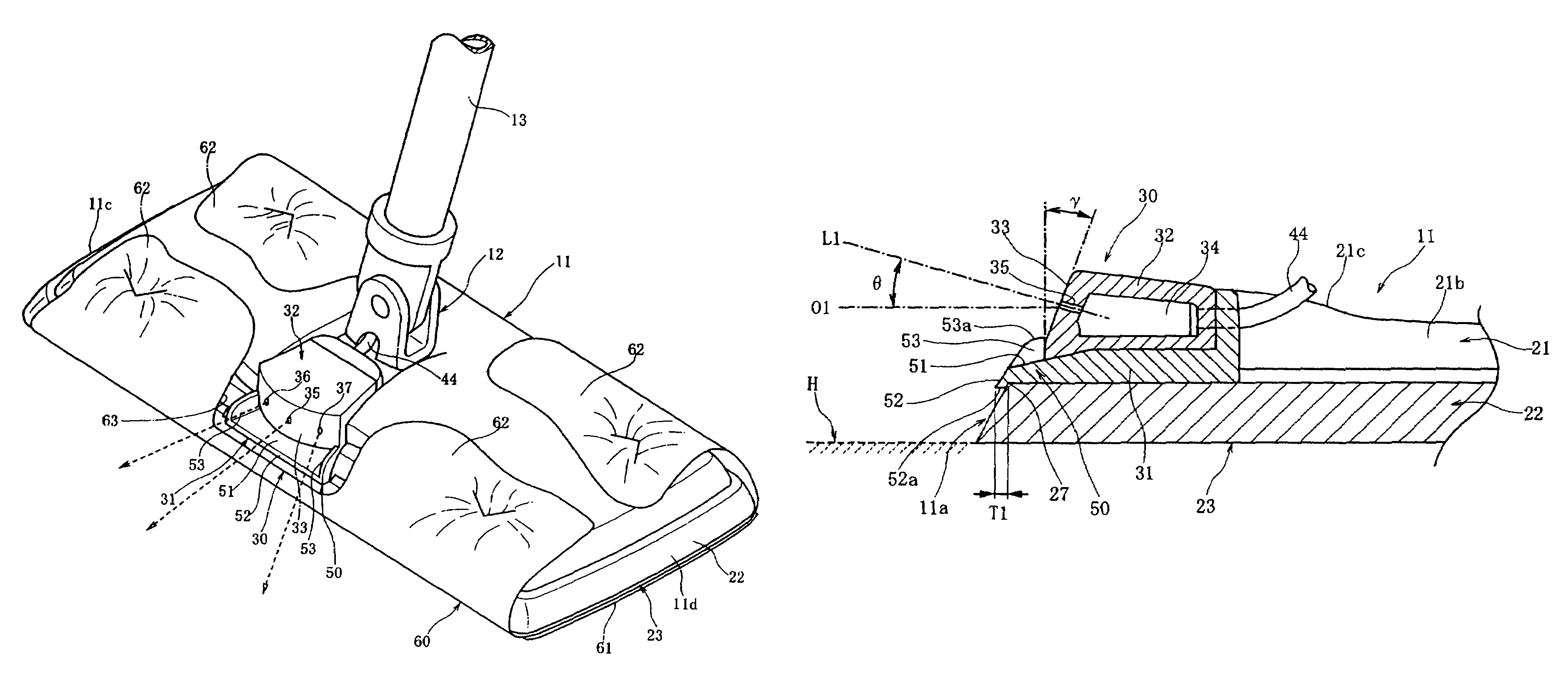
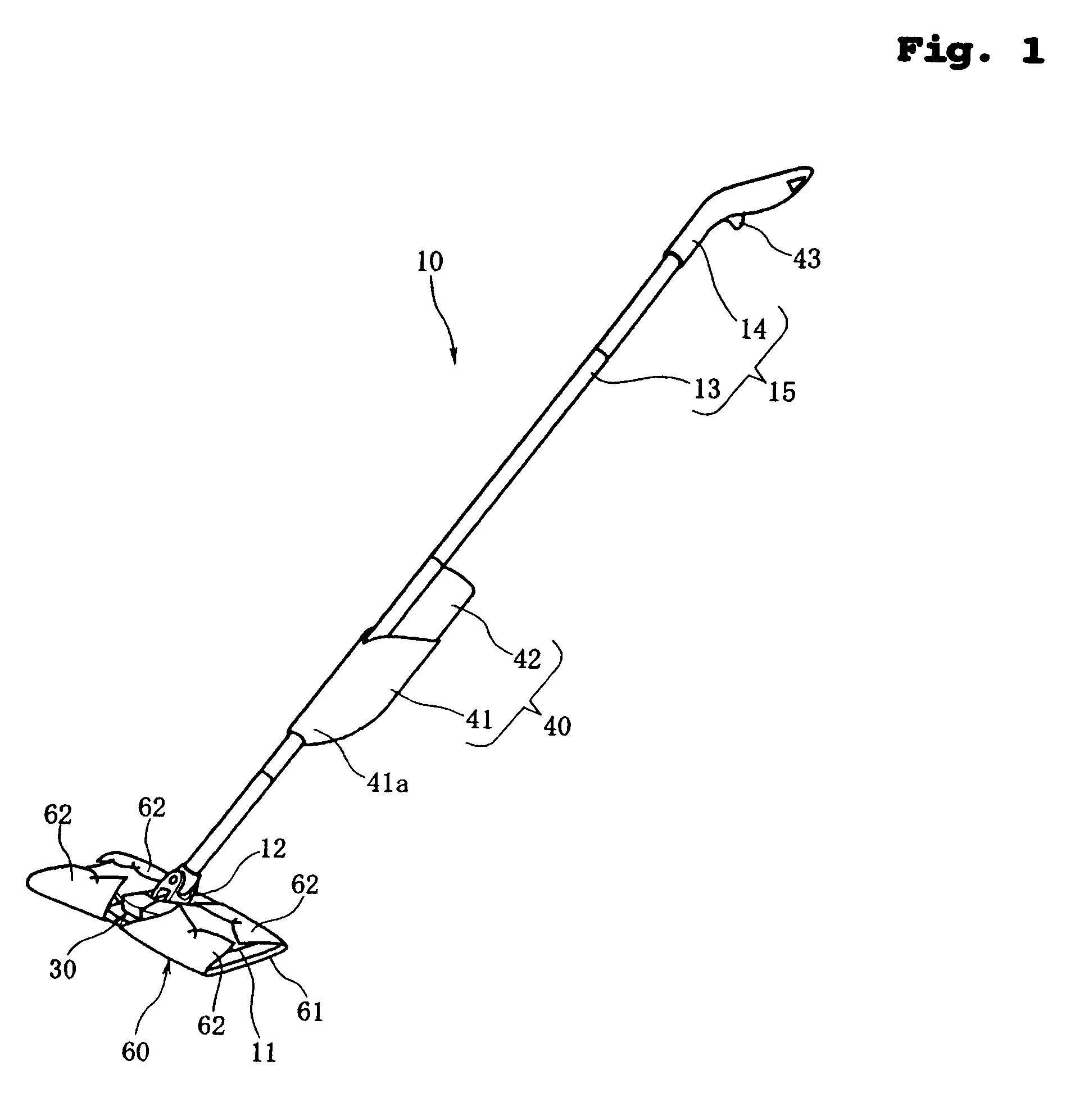
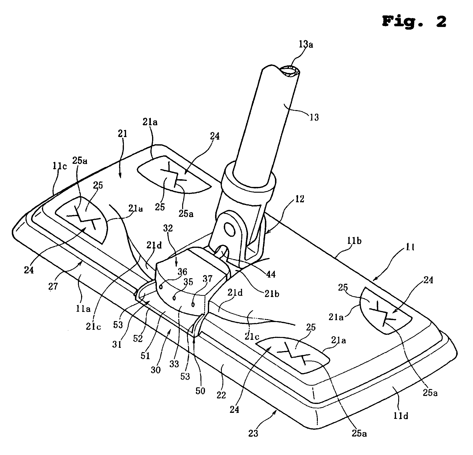
[0036]FIG. 1 is a perspective view of a cleaning device 10 according to the present invention; FIG. 2 is an enlarged perspective view showing a cleaning head; FIG. 3 is a perspective view showing a state where a disposable cleaning sheet is removably attached to the cleaning head; FIG. 4 is an enlarged plan view showing a liquid jetting part mounted on the cleaning head; FIG. 5 is a front view of the liquid jetting part; and FIG. 6 is a sectional view taken along line VI-VI of FIG. 5.

[0037]As shown in FIG. 1, the cleaning device 10 comprises a cleaning head 11, a shaft 13 connected to the top face of the cleaning head 11 through a universal joint 12, and a grip 14 secured on the top end of the shaft 13. In the present embodiment, the shaft 13 and the grip 14 constitute a handle 15.

[0038]As viewed from above (FIG. 2), the cleaning head 11 has a generally rectangular contour. The cleaning head 11 has a front face 11a along one longer side of the rectangle and a rear face 11b along the...

second embodiment

[0085]FIG. 7 is a plan view showing a nozzle head 132 of a cleaning device according to the present invention.

[0086]The nozzle head 132 has a squirt surface 133 whose contour in the plan view of FIG. 7 is different from that of the squirt surface 33 of the nozzle head 32 according to the first embodiment. The other portions have the same construction as those of the first embodiment.

[0087]In FIG. 7, the squirt surface 133 has a location 133a where a nozzle 135 has an orifice, a location 133b where a nozzle 136 has an orifice, and a location 133c where a nozzle 137 has an orifice. The location 133a is a plane perpendicular to the reference line O1-O2, the location 133b is a plane coinciding with the tangent PL2 of FIG. 4, and the location 133c is a plane coinciding with the tangent PL3 of FIG. 4. The preferred ranges of the squirt angles α1, α2 of the squirt directions L2, L3 and the opening angles β1, β2 of the locations 133b, 133c and the relationships between these angles are the ...


PUM


Abstract

Disclosed is a cleaning device with a squirter for squirting liquid forward of a cleaning head. The cleaning head has a nozzle head with a nozzle. A liquid receiving part is provided to extend from beneath an orifice of the nozzle toward a front face of the cleaning head. Liquid dripping from the orifice of the nozzle can be led down an inclined top face of the liquid receiving part to the outside of the cleaning head, preventing the cleaning head from being soiled with a detergent, a wax or the like.

Description

BACKGROUND OF THE INVENTION[0001]1. Field of the Invention[0002]The present invention relates to a cleaning device suitable for cleaning a floor surface of a house, an office, etc., and more particularly to a cleaning device with a squirter for squirting liquid toward an object to be cleaned such as a floor surface.[0003]2. Description of the Related Art[0004]Japanese Utility-Model Registration No. 3094858 discloses a cleaning device having a mop section at one end of a handle constructed by connecting pipes together. The mop section has nozzles and the handle is equipped with a water container. The handle has a handle switch in its grip. By operating the handle switch, a piston provided in the water container is moved to squirt water out of the water container through the nozzles. This utility-model is aimed at improving the effect of cleaning the floor by squirting water from the nozzles.[0005]Japanese Utility-Model Registration No. 3094858 does not specify the construction around...

Claims


Application Information

Patent Timeline
Patent Type & Authority Patents(United States)
IPC IPC(8): A47L13/26A47L13/22A47L13/254
CPCA47L13/22A47L13/20
Inventor SUDA, TOMOKAZUTANAKA, YOSHINORIFUJIWARA, MASATOSHI
Owner UNI CHARM CORP
Why Eureka
Try Eureka