Ultrasonic treatment equipment

a treatment equipment and ultrasonic technology, applied in the field of ultrasonic treatment equipment, can solve the problems of increasing the treatment time, increasing the treatment efficiency, and remarkably low treatment efficiency in particular for tumors with a large volume, such as uterine fibroid, and ensuring the coagulation effect on the blood vessel is not kept constan

Inactive Publication Date: 2010-04-20
HITACHI LTD +1
View PDF10 Cites 13 Cited by
  • Summary
  • Abstract
  • Description
  • Claims
  • Application Information

AI Technical Summary

Benefits of technology

[0008]Recently, as a method for treating uterine fibroid, liver cancer, and the like, the arterial embolization therapy is being tried. This treatment method involves inserting a catheter into a feeding vessel of the tumor and injecting an infarction material into the blood vessel. The injected infarction material blocks the feeding vessel that returns to the tumor, which interrupts the blood flow. As a result, furnishing of nutrition to the tumor is stopped, and thus the tumor is treated. In general, it is known that as a tumor such as uterine fibroid has a smaller amount of blood flow, tumor regression effects produced by the interruption of the blood flow become stronger. This treatment method, however, involves inserting a catheter from a main artery located at the base of the thigh or the like of a patient under general anesthesia or local anesthesia, and introducing the catheter up to a blood vessel of a target region under fluoroscopy. Accordingly, the patient is much exposed to X-radiation, and much suffers from the insertion of the catheter.
[0010]An object of the present invention is to provide ultrasonic treatment equipment that is capable of repeating exposure to a therapeutic ultrasonic wave while measuring a degree of vessel constriction on a therapeutic ultrasound exposure basis.
[0012]The ultrasonic treatment equipment according to the present invention measures the blood flow velocity of the blood vessel to which the therapeutic ultrasonic wave has been exposed, and then compares the blood flow velocity before the exposure to the therapeutic ultrasonic wave with that after the exposure to the therapeutic ultrasonic wave, thereby making it possible to evaluate a degree of constriction of the blood vessel or a degree of infarction of the blood vessel, and to recognize whether or not the blood vessel has been correctly exposed to the therapeutic ultrasonic wave.
[0013]To be more specific, as a result of aiming at a blood vessel region and exposing the blood vessel in the region to the therapeutic ultrasonic wave, if there is a substantial change in blood flow velocity that indicates predetermined constriction of the blood vessel, it can be judged that this ultrasound exposure is correctly aimed at the blood vessel and accordingly the ultrasound exposure is effective. Therefore, repeating the ultrasound exposure in the same region makes it possible to efficiently promote the constriction of the blood vessel in stages. To be more specific, by repeating the exposure while making a judgment as to whether or not the exposure has caused the vessel constriction on the basis of a change in blood flow velocity on an ultrasound exposure basis, it is possible to achieve the vessel infarction, and thereby to interrupt feeding vessels of the tumor.

Problems solved by technology

Thus, the current heat coagulation therapy has a large problem of the increased treatment time.
Under the existing circumstances, there is a problem in that, for example, the treatment efficiency in particular for a tumor with a large volume, such as uterine fibroid, is remarkably low.
Further, when HIFU is aimed at a blood vessel for exposure, coagulation effects on the blood vessel are not kept constant.
Under the existing circumstances, there is another problem in that it is not possible to judge effects on blood vessels on a HIFU basis.
Accordingly, the patient is much exposed to X-radiation, and much suffers from the insertion of the catheter.

Method used


Image

  • Ultrasonic treatment equipment
  • Ultrasonic treatment equipment
  • Ultrasonic treatment equipment

Examples


Embodiment Construction

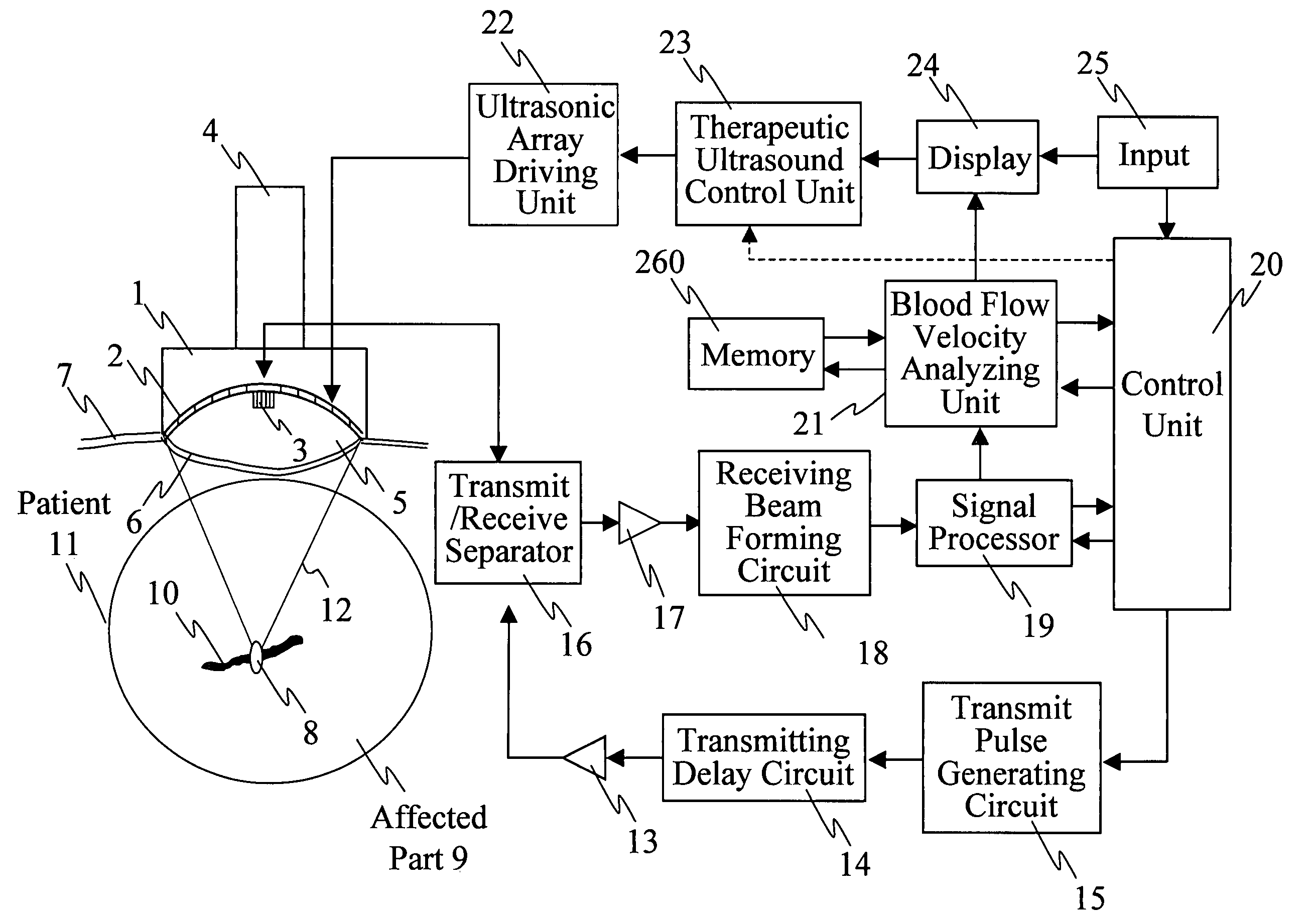
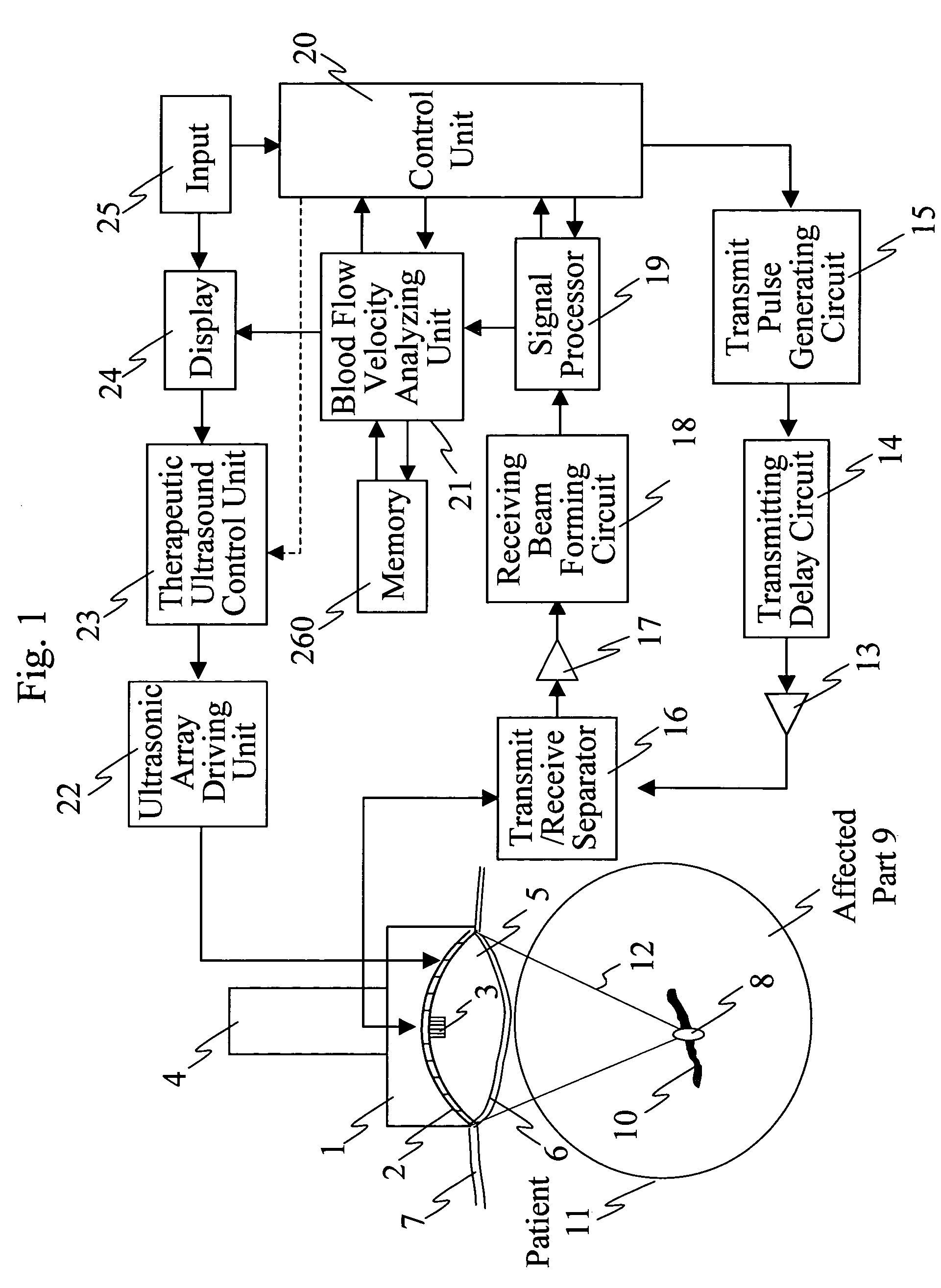
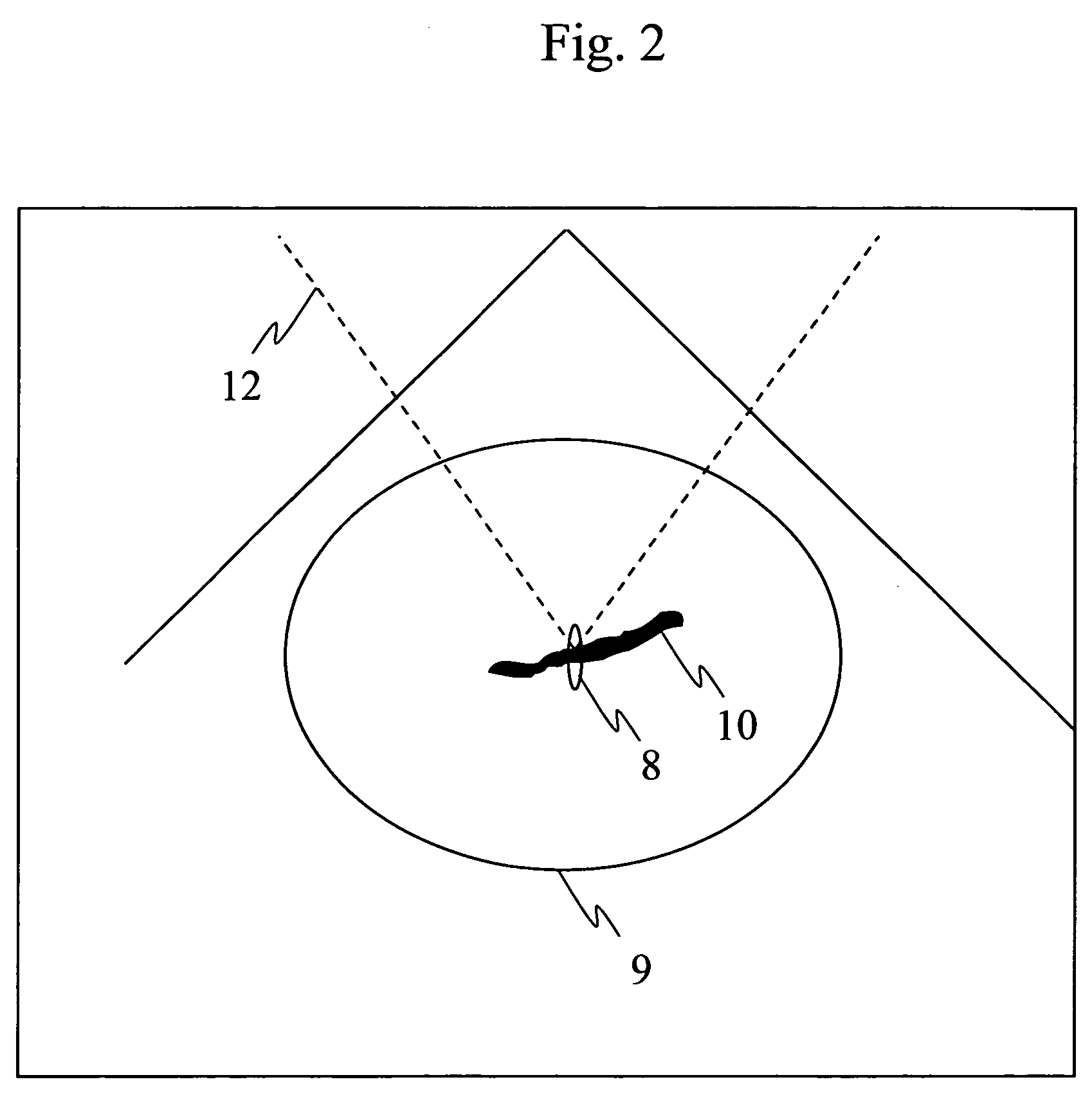
[0025]In ultrasonic treatment equipment according to the present invention, therapeutic ultrasound exposure is repeated a plurality of times while measuring a degree of vessel constriction on a therapeutic ultrasound exposure basis.

[0026]Ultrasonic treatment equipment according to a first configuration of the present invention comprises: a therapeutic ultrasonic transducer which exposes a blood vessel of an affected part to a focused therapeutic ultrasonic wave for a specified period of exposure time; an imaging ultrasonic probe which images an ultrasound tomographic image of the affected part; a display unit which displays the ultrasound tomographic image; means for comparing the blood flow velocity of the blood vessel before the exposure to the therapeutic ultrasonic wave with that after the exposure to the therapeutic ultrasonic wave, and thereby calculating a rate of change in blood flow velocity, wherein the therapeutic ultrasonic wave exposure causes the blood vessel of the af...


PUM


Abstract

Ultrasonic treatment equipment is provided which repeats therapeutic ultrasound exposure while measuring a degree of vessel constriction on a therapeutic ultrasound exposure basis. This equipment includes: a therapeutic ultrasonic transducer 2 which exposes a blood vessel of an affected part to a focused therapeutic ultrasonic wave for a specified period of exposure time; an imaging ultrasonic probe 3 which images an ultrasound tomographic image of the affected part; a display unit 24 which displays the ultrasound tomographic image; means 21 for detecting a blood flow signal from a signal received by the imaging ultrasonic probe and determining the blood flow velocity of the blood vessels of the affected part; means 21 for calculating a rate of change in blood flow velocity during the exposure to the therapeutic ultrasonic wave or before and after the exposure to the therapeutic ultrasonic wave; and means 23 for controlling exposure conditions of the therapeutic ultrasonic wave on the basis of the rate of change in blood flow velocity, and thereby controlling the therapeutic ultrasonic transducer.

Description

FIELD OF THE INVENTION[0001]The present invention relates to ultrasonic treatment equipment used for treating tumors.BACKGROUND OF THE INVENTION[0002]Ultrasonic waves have characteristics that electromagnetic waves such as a laser beam and a microwave never provide in that the former deeply propagates inside a living-body at short wavelengths and can be focused on an arbitrary point. Research and development of ultrasonic therapy which make good use of these characteristics have been actively advanced. The effects of ultrasonic waves on a living body, which can be made use of at the time of treatment, are roughly classified into thermal effects and sonochemical effects. The former thermal effects are produced when tissue absorbs an ultrasonic wave and consequently heat is generated. The treatments that medically use the thermal effects are roughly classified into “hyperthermia” and “heat coagulation therapy”. Hyperthermia involves continuously heating an affected part to about 40 to...

Claims


Application Information

Patent Timeline
Patent Type & Authority Patents(United States)
IPC IPC(8): A61B8/00A61B8/06A61B8/13A61B19/00A61N7/02
CPCA61N7/02A61B8/06A61B2019/5276A61B8/13A61B2090/378
Inventor SASAKI, KAZUAKIAZUMA, TAKASHIKAWABATA, KEN-ICHIUMEMURA, SHIN-ICHIROOKAI, TAKASHIISHIKAWA, TETSUYA
Owner HITACHI LTD
Why Eureka
Try Eureka