Ultrasonic treatment equipment

a treatment equipment and ultrasonic technology, applied in the field of ultrasonic treatment equipment, can solve the problems of increasing treatment time, affecting the treatment effect, and affecting the treatment efficiency of uterine fibroid tumors, and achieving the effect of efficient promotion of blood vessel constriction

Inactive Publication Date: 2007-07-12
HITACHI LTD +1
View PDF8 Cites 25 Cited by
  • Summary
  • Abstract
  • Description
  • Claims
  • Application Information

AI Technical Summary

Benefits of technology

[0012] The ultrasonic treatment equipment according to the present invention measures the blood flow velocity of the blood vessel to which the therapeutic ultrasonic wave has been exposed, and then compares the blood flow velocity before the exposure to the therapeutic ultrasonic wave with that after the exposure to the therapeutic ultrasonic wave, thereby making it possible to evaluate a degree of constriction of the blood vessel or a degree of infarction of the blood vessel, and to recognize whether or not the blood vessel has been correctly exposed to the therapeutic ultrasonic wave.
[0013] To be more specific, as a result of aiming at a blood vessel region and exposing the blood vessel in the region to the therapeutic ultrasonic

Problems solved by technology

Thus, the current heat coagulation therapy has a large problem of the increased treatment time.
Under the existing circumstances, there is a problem in that, for example, the treatment efficiency in particular for a tumor with a large volume, such as uterine fibroid, is remarkably low.
Further, when HIFU is aimed at a blood ve

Method used


Image

  • Ultrasonic treatment equipment
  • Ultrasonic treatment equipment
  • Ultrasonic treatment equipment

Examples


Embodiment Construction

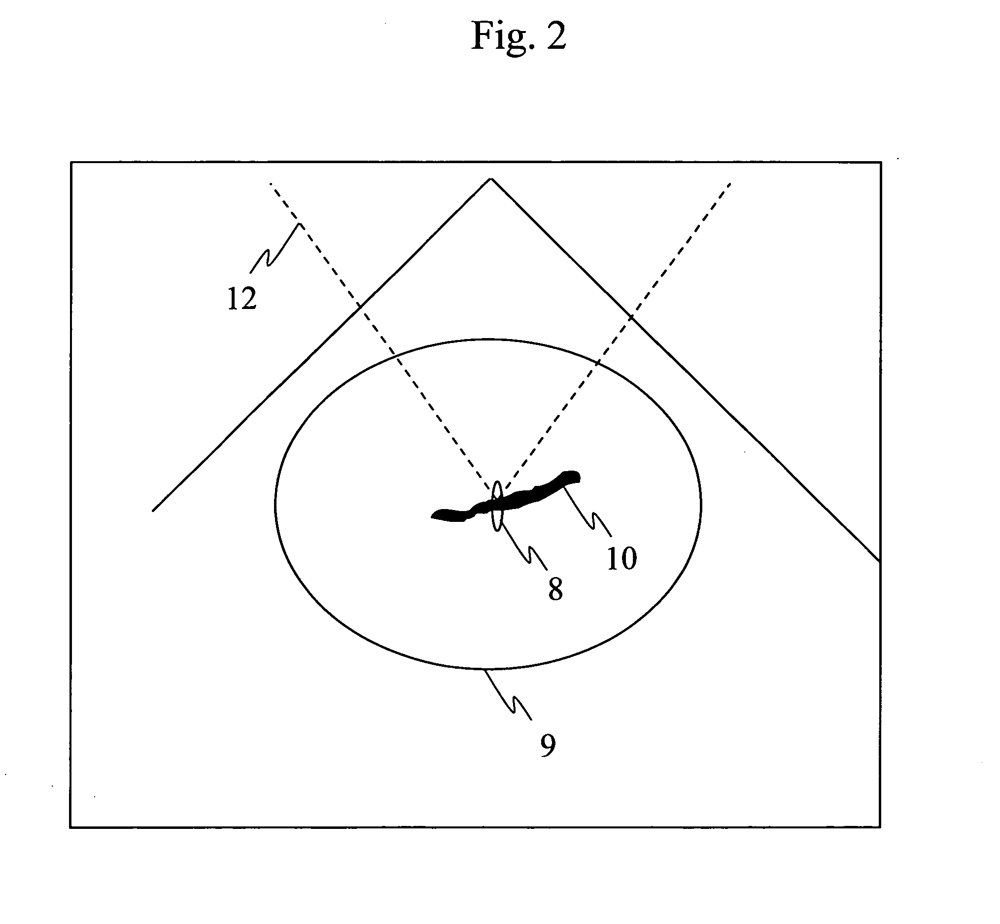
[0025] In ultrasonic treatment equipment according to the present invention, therapeutic ultrasound exposure is repeated a plurality of times while measuring a degree of vessel constriction on a therapeutic ultrasound exposure basis.

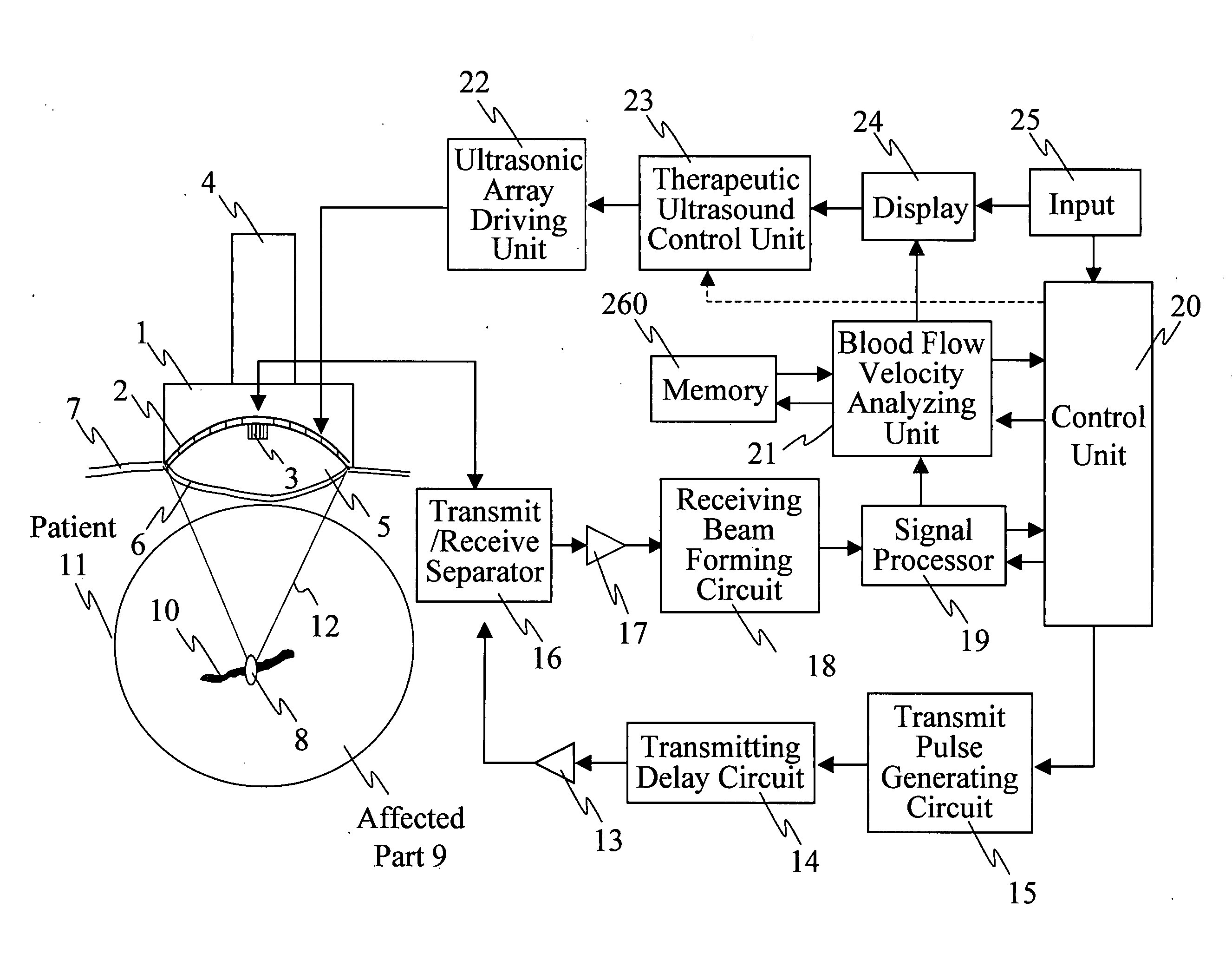
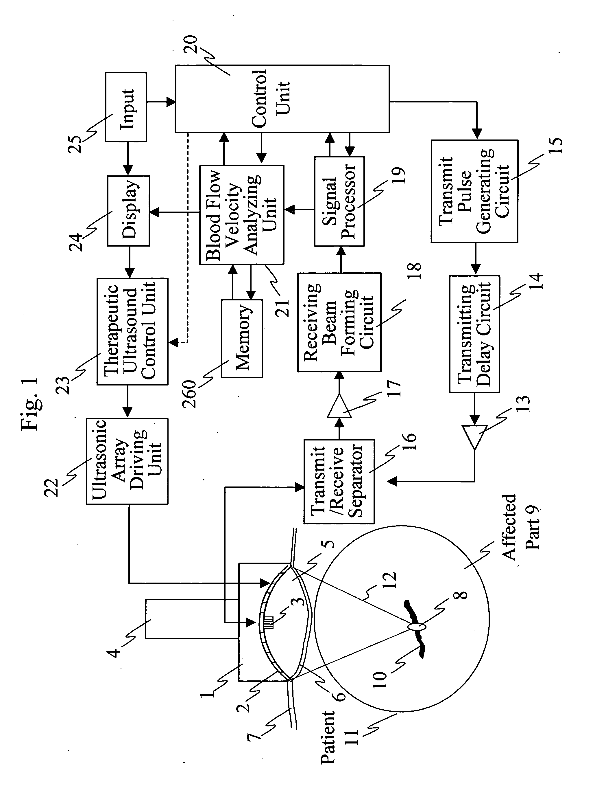
[0026] Ultrasonic treatment equipment according to a first configuration of the present invention comprises: a therapeutic ultrasonic transducer which exposes a blood vessel of an affected part to a focused therapeutic ultrasonic wave for a specified period of exposure time; an imaging ultrasonic probe which images an ultrasound tomographic image of the affected part; a display unit which displays the ultrasound tomographic image; means for comparing the blood flow velocity of the blood vessel before the exposure to the therapeutic ultrasonic wave with that after the exposure to the therapeutic ultrasonic wave, and thereby calculating a rate of change in blood flow velocity, wherein the therapeutic ultrasonic wave exposure causes the blood vessel of the...


PUM


Abstract

Ultrasonic treatment equipment is provided which repeats therapeutic ultrasound exposure while measuring a degree of vessel constriction on a therapeutic ultrasound exposure basis. This equipment includes: a therapeutic ultrasonic transducer 2 which exposes a blood vessel of an affected part to a focused therapeutic ultrasonic wave for a specified period of exposure time; an imaging ultrasonic probe 3 which images an ultrasound tomographic image of the affected part; a display unit 24 which displays the ultrasound tomographic image; means 21 for detecting a blood flow signal from a signal received by the imaging ultrasonic probe and determining the blood flow velocity of the blood vessels of the affected part; means 21 for calculating a rate of change in blood flow velocity during the exposure to the therapeutic ultrasonic wave or before and after the exposure to the therapeutic ultrasonic wave; and means 23 for controlling exposure conditions of the therapeutic ultrasonic wave on the basis of the rate of change in blood flow velocity, and thereby controlling the therapeutic ultrasonic transducer.

Description

FIELD OF THE INVENTION [0001] The present invention relates to ultrasonic treatment equipment used for treating tumors. BACKGROUND OF THE INVENTION [0002] Ultrasonic waves have characteristics that electromagnetic waves such as a laser beam and a microwave never provide in that the former deeply propagates inside a living-body at short wavelengths and can be focused on an arbitrary point. Research and development of ultrasonic therapy which make good use of these characteristics have been actively advanced. The effects of ultrasonic waves on a living body, which can be made use of at the time of treatment, are roughly classified into thermal effects and sonochemical effects. The former thermal effects are produced when tissue absorbs an ultrasonic wave and consequently heat is generated. The treatments that medically use the thermal effects are roughly classified into “hyperthermia” and “heat coagulation therapy”. Hyperthermia involves continuously heating an affected part to about ...

Claims


Application Information

Patent Timeline
IPC IPC(8): A61B8/00A61B8/06A61B8/13A61B19/00A61N7/02
CPCA61B8/06A61N7/02A61B2019/5276A61B8/13A61B2090/378
Inventor SASAKI, KAZUAKIAZUMA, TAKASHIKAWABATA, KEN-ICHIUMEMURA, SHIN-ICHIROOKAI, TAKASHIISHIKAWA, TETSUYA
Owner HITACHI LTD
Why Eureka
Try Eureka