Movable body system, pattern formation apparatus, exposure apparatus and measurement device, and device manufacturing method

a technology of movement body and pattern, applied in the direction of photomechanical equipment, instruments, printers, etc., can solve the problems of encoder head interfering with dragging such wiring, and affecting the smooth movement of the substrate table, so as to achieve good precision

Active Publication Date: 2009-06-25
NIKON CORP
View PDF31 Cites 27 Cited by
  • Summary
  • Abstract
  • Description
  • Claims
  • Application Information

AI Technical Summary

Benefits of technology

[0010]According to the movable body system of the present invention, the measurement device has a transmitting and receiving equipment which performs transmitting and receiving of a measurement beam and / or a signal by wireless communication between each of the plurality of encoder heads arranged on the table member and a component outside the encoder heads. Therefore, even if the main section of the movable body moves along a predetermined plane, and the table member also moves finely in a direction orthogonal to the predetermined plane, measurement light and transmitting and receiving of the measurement beam and / or the signal between each of the plurality of encoder heads and the component outside the encoder heads can be performed without any problems. Accordingly, positional information of the movable body within the predetermined plane can be measured with good precision, without being affected by the fine movement of the table member.
[0012]According to the exposure apparatus of the present invention, the measurement device has a transmitting and receiving equipment which performs transmitting and receiving of a measurement beam and / or a signal by wireless communication between each of the plurality of encoder heads arranged on the table members which holds the object and is movable in the direction orthogonal to the predetermined plane, and the component outside the encoder heads. Further, the table member is supported in a non-contact manner by the main section of the stage assembly. Therefore, in the case the main section of the stage assembly moves along a predetermined plane, and the table member also moves finely in a direction orthogonal to the predetermined plane, measurement light and transmitting and receiving of the measurement beam and / or the signal between each of the plurality of encoder heads and the component outside the encoder heads can be performed without any problems by wireless communication. Accordingly, the position of the stage assembly related to the predetermined plane can be obtained with good precision, without being affected by the fine movement of the table member, which in turn makes it possible to perform exposure with high precision of the object held by the table member, while controlling the position of the stage assembly within the predetermined plane with high precision on exposure.
[0014]According to the measurement device of the present invention, positional information of the table member within a predetermined plane can be measured with good precision, without being affected by the fine movement of the table member in the direction orthogonal to the predetermined plane.

Problems solved by technology

However, in the case when an encoder head is installed on the substrate table, because the substrate table performs a vertical and inclined movement, there was a risk of the tension which acts on wiring for supplying power and the like to the encoder head interfering with the smooth movement of the substrate table.
In the case when a plurality of encoder heads is installed on the substrate table, dragging of such wiring could become a major obstacle.

Method used


Image

  • Movable body system, pattern formation apparatus, exposure apparatus and measurement device, and device manufacturing method
  • Movable body system, pattern formation apparatus, exposure apparatus and measurement device, and device manufacturing method
  • Movable body system, pattern formation apparatus, exposure apparatus and measurement device, and device manufacturing method

Examples


first embodiment

A First Embodiment

[0024]Hereinafter, a first embodiment of the present invention will be described with reference to FIGS. 1 to 6.

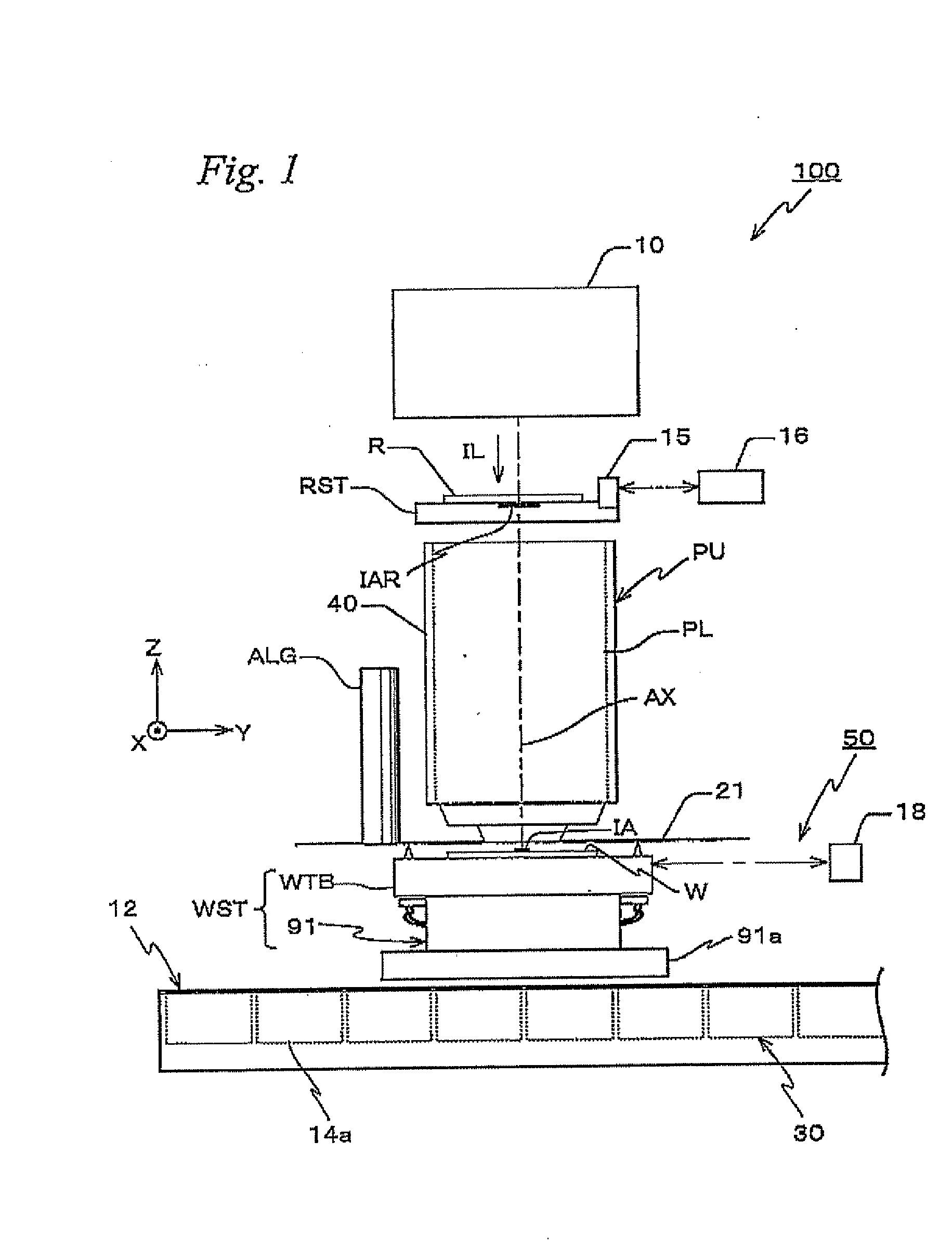
[0025]FIG. 1 shows a schematic configuration of an exposure apparatus 100 in the first embodiment. Exposure apparatus 100 is a projection exposure apparatus of the step-and-scan method, namely the so-called scanner. As it will be described later, a projection optical system PL is arranged in the embodiment, and in the description below, a direction parallel to an optical axis AX of projection optical system PL will be described as the Z-axis direction, a direction within a plane orthogonal to the Z-axis direction in which a reticle and a wafer are relatively scanned will be described as the Y-axis direction, a direction orthogonal to the Z-axis and the Y-axis will be described as the X-axis direction, and rotational (inclination) directions around the X-axis, the Y-axis, and the Z-axis will be described as θx, θy, and θz directions, respectively.

[0026]Exp...

second embodiment

A Second Embodiment

[0072]Next, a second embodiment of the present invention will be described, referring to FIGS. 7 and 8. Here, the same reference numerals will be used for the same or similar sections as in the first embodiment previously described, and a detailed description thereabout will be omitted. The exposure apparatus of the second embodiment differ only in a part of the configuration inside each encoder head which differs when compared with the exposure apparatus of the first embodiment previously described and the point where optical fiber 26 is not arranged, and with such configurations, the point where a receiver 32 is arranged at stage main section 91 (or, at other appropriate places external to the encoder head) of wafer stage WST. Accordingly, the exposure apparatus of the second embodiment will be described below, focusing mainly on such differences.

[0073]As is shown in FIG. 7, focusing on head 60C as a representative, outside the lower end surface of fiber housing...


PUM


Abstract

A movable body system is equipped with a stage having a stage main section which moves along an XY plane and a stage which is finely movable in a direction (a Z-axis direction) orthogonal to the XY plane and a tilt direction with respect to the XY plane, and a measurement device which measures positional information of the stage within the XY plane. The measurement device has a plurality of encoder heads arranged on the table, and optical fibers whose end sections are arranged facing each head at the stage main section and the optical axes at the end sections are substantially parallel to the Z-axis direction, and the device measures positional information of the stage, based on an output of a head facing a grating section placed substantially parallel to the XY plane. And, air transmission of a signal is performed between each of the heads and the end section of the optical fibers.

Description

CROSS-REFERENCE TO RELATED APPLICATIONS[0001]This non-provisional application claims the benefit of Provisional Application No. 61 / 006,818 filed Jan. 31, 2008, and Provisional Application No. 61 / 071,683 filed May 22, 2009, the disclosures of which are hereby incorporated herein by reference in its entirety.BACKGROUND OF THE INVENTION[0002]1. Field of the Invention[0003]The present invention relates to movable body systems, pattern formation apparatus, exposure apparatus and measurement devices, and device manufacturing methods, and more particularly, to a movable body system including a movable body which substantially moves along a predetermined plane, a pattern formation apparatus which is equipped with the movable body system, an exposure apparatus which is equipped with the movable body system, a measurement device arranged in an exposure apparatus, and a device manufacturing method which uses the exposure apparatus.[0004]2. Description of the Background Art[0005]Conventionally,...

Claims


Application Information

Patent Timeline
Patent Type & Authority Applications(United States)
IPC IPC(8): G03B27/42G01B11/14
CPCG01D5/34723G03F7/70775G01D5/34746G01D2205/90G03F7/70716G03F7/70758
Inventor SHIBAZAKI, YUICHI
Owner NIKON CORP
Why Eureka
Try Eureka