Motion estimation or P-type images using direct mode prediction

a technology of motion estimation and p-type images, applied in the field ofdifferential coding of image blocks, can solve the problems of data compression and consequently not optimal for these images of bidirectional type, and achieve the effect of zero cos

Active Publication Date: 2010-04-20
INTERDIGITAL MADISON PATENT HLDG
View PDF11 Cites 54 Cited by
  • Summary
  • Abstract
  • Description
  • Claims
  • Application Information

AI Technical Summary

Benefits of technology

[0032]The advantages of the invention relate to the improving of the quality of the regulated throughput image as well as a lower cost at constant quality. The choice between several types of SAD, during the selection of the vectors of the P image, substantially increases the homogeneity of the motion field.
[0034]The process makes it possible to favour, during the coding of the B images, the direct mode which generally represents the most economical mode for this type of image in terms of coding cost. This direct mode can, under certain conditions, lead to the “skipped macroblock” mode (for example described in §7.6.6 of the ISO 13818-2 standard) which is a mode of coding corresponding to a zero residual, at almost zero cost.

Problems solved by technology

The coding, that is to say the data compression, is consequently not optimal for these images of bidirectional type.

Method used


Image

  • Motion estimation or P-type images using direct mode prediction
  • Motion estimation or P-type images using direct mode prediction
  • Motion estimation or P-type images using direct mode prediction

Examples


Embodiment Construction

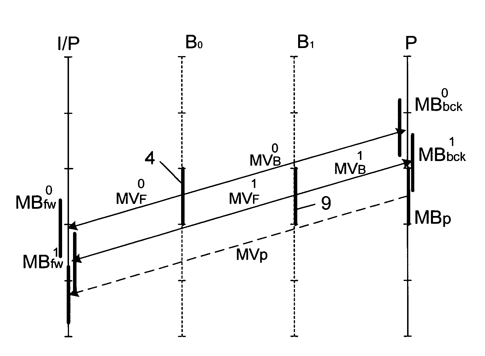
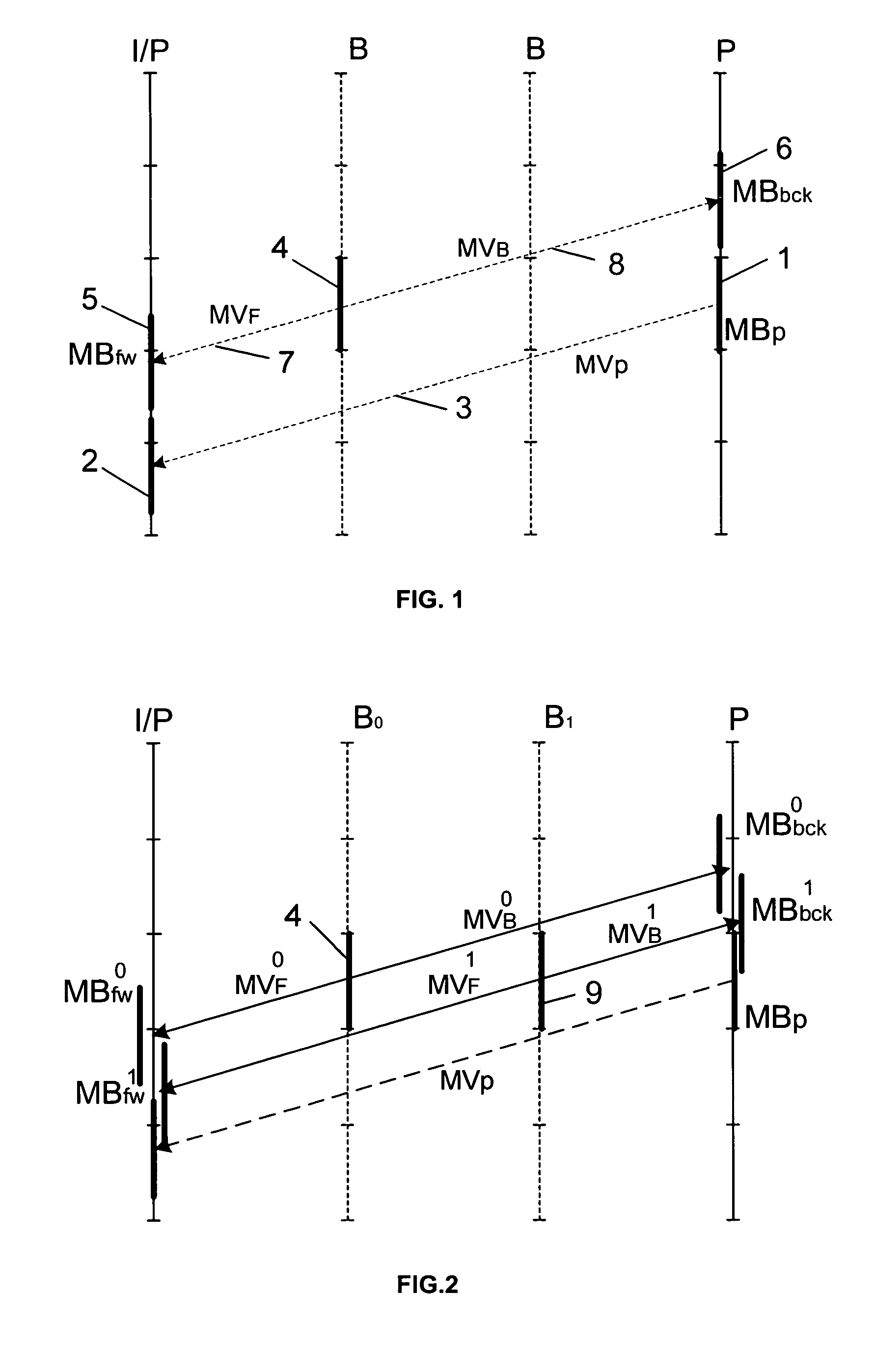
[0038]FIG. 2 represents the prediction for a current block MBp of a P image as well as the predictions of direct type for the co-located blocks belonging to the images of type B, a first image called B0 and a second image called B1.

[0039]The terms previously used are indexed zero or one depending on whether they relate to the first image Bo or the second image B1.

[0040]Thus, as far as the image Bo is concerned, the motion vectors 7 and 8 are labelled MVF0 and MVB0 and respectively designate the predicted blocks MBfw0, MBbck0 for the reference images I / P and P.

[0041]The motion vectors corresponding to the image B1 are labelled MVF1 and MVB1 and respectively designate the predicted blocks MBfw1, MBbck1 for the reference images I / P and P.

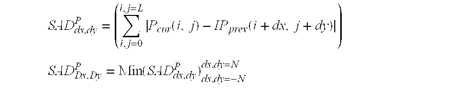
[0042]In this context where two images of type B lie between the reference images I / P and P, on the basis of the calculation of the SAD, a conceivable criterion for selecting the motion vector MVp corresponding to the block of the P image becomes:

[0043...


PUM


Abstract

The process for coding the current block comprises a step of selecting the predicted block from among candidate blocks, the selection being dependent on a difference DBdrx,dry between the co-located block of the current image block lying in an image of type B and the block of a reference image, the latter block being designated by the motion vector with components drx, dry which is allocated to co-located block and which is colinear with the motion vector Vp allocated to the current block and designating the candidate block. The process relates to data compression, the transmission of digital images using the video coding standard comprising a direct prediction mode, for example the h263, MPEG4 or h261 standard.

Description

[0001]This application claims the benefit, under 35 U.S.C. 119, of France patent application No. 0350629 filed Oct. 1, 2003.FIELD OF THE INVENTION[0002]The invention relates to a process and a device for the differential coding of an image block with predictive coding. It relates more particularly to coding processes or devices utilizing the “direct” mode. As explained later, the “direct” mode is a bidirectional mode of prediction utilizing motion compensation, the components of whose motion vectors are derived from the components of the motion vector used for the coding of the co-located macroblock of a subsequent predictive-coding image.[0003]The field is that of video compression and most particularly that of the video coding of the MPEG 4 part 2 or part 10, H.263 and H.261 type.BACKGROUND OF THE INVENTION[0004]In data compression standards, for example of MPEG type, the images to be coded are generally images of intra and inter type and in the latter case, with predictive coding...

Claims


Application Information

Patent Timeline
Patent Type & Authority Patents(United States)
IPC IPC(8): G06K9/36G06K9/46H03M7/36H04N7/24H04N19/50
CPCH04N19/51H04N19/577H04N19/61
Inventor THOREAU, DOMINIQUEFRANCOIS, EDOUARDRUELLOU, PIERRE
Owner INTERDIGITAL MADISON PATENT HLDG
Why Eureka
Try Eureka