
Clog resistant pilot valve

a pilot valve and clog-resistant technology, applied in the direction of valve details, valve arrangement, operating means/releasing devices, etc., can solve the problems of pilot valve failure and seize of plunger assembly, and achieve the effect of reducing the probability of pilot valve failure and reducing the probability of contaminates accumulating

Active Publication Date: 2010-04-27
FRLIN ROBERT C
View PDF7 Cites 40 Cited by
  • Summary
  • Abstract
  • Description
  • Claims
  • Application Information

AI Technical Summary

Benefits of technology

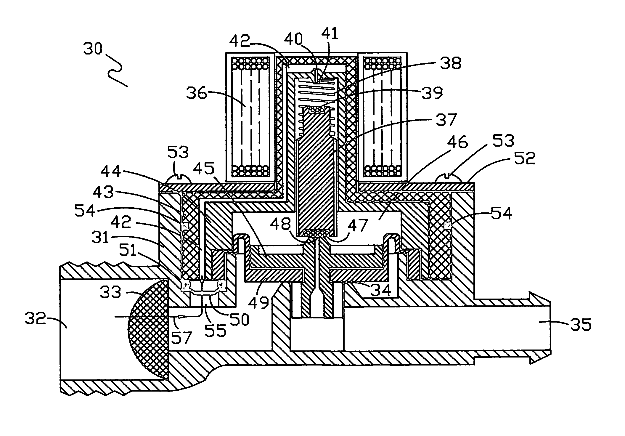
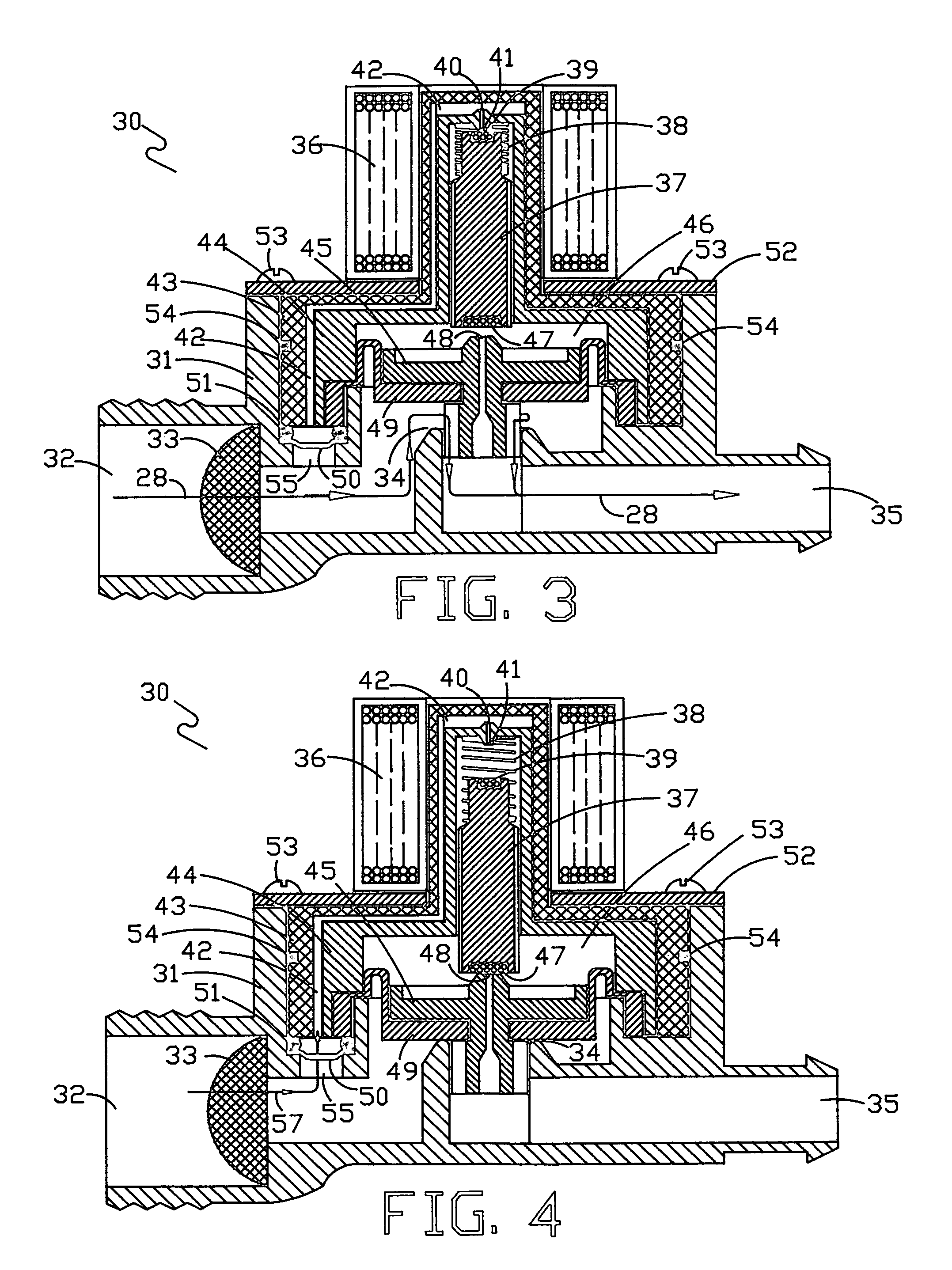
[0006]The present invention involves two improvements to existing pilot valve technology. First, this invention reduces the probability of pilot valve failure by totally blocking fluid flow through the pilot apertures when the pilot valve is in an open condition, allowing fluid to flow from the valve input port to the output port. Fluid will flow through the input pilot aperture only during the transition from a valve open to valve closed condition. This typically occurs within a fraction of a second. As part of this first improvement, the fluid filter provision of the input pilot aperture is moved from the standard location in the flexible diaphragm assembly to a location adjacent to the valve input port. This provision not only allows the use of standard filter screen material, that provides a larger number of effective filter holes, but also places the filter in a location in which higher velocity fluid flow will tend to reduce the accumulation of contaminant materials on the filter screen. The second improvement involves changing the physical shape of the plunger assembly that is used to open and close the outlet pilot aperture. Accumulation of contaminants between the outer diameter of the plunger assembly and the adjacent housing in which the plunger assembly moves has been shown to be another source of pilot valve failure. Such accumulation of contaminants can cause the plunger assembly to seize in a position that holds the pilot valve in either an open or closed condition. It will be seen later that adding a ribbed external surface to the plunger assembly will reduce the probability that contaminates can accumulate and restrict the movement of the plunger assembly.

Problems solved by technology

Accumulation of contaminants between the outer diameter of the plunger assembly and the adjacent housing in which the plunger assembly moves has been shown to be another source of pilot valve failure.
Such accumulation of contaminants can cause the plunger assembly to seize in a position that holds the pilot valve in either an open or closed condition.

Method used


Image

  • Clog resistant pilot valve
  • Clog resistant pilot valve
  • Clog resistant pilot valve

Examples


Embodiment Construction

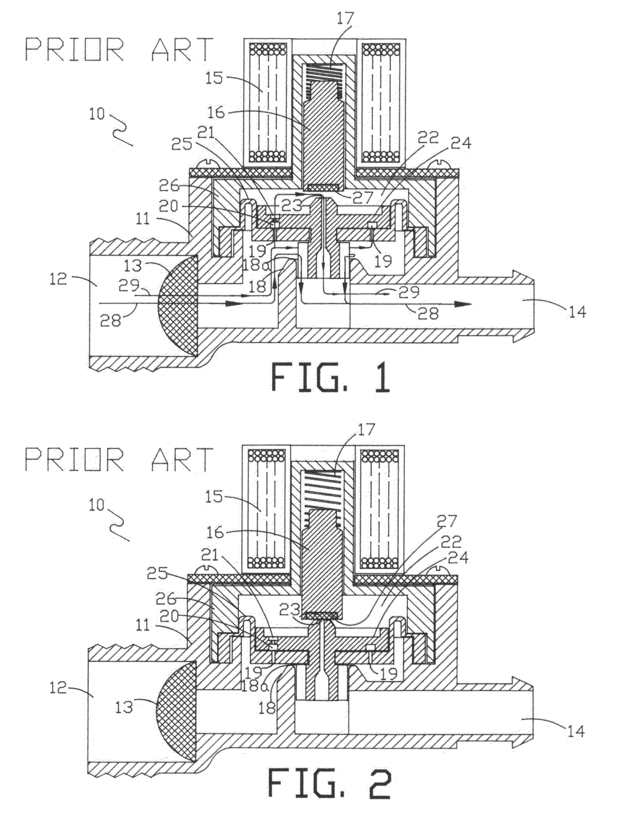
[0020]FIG. 1 shows a typical pilot valve assembly 10 with a valve body 11 having an input port 12 with a filter screen 13 and an output port 14. In the present condition, solenoid 15 is assumed to be energized by an external voltage source, not shown: This causes the plunger assembly 16, fabricated from ferromagnetic material, to be pulled into the shown position by the magnetic field attraction generated by the energized solenoid 15. Spring 17 located on the top of plunger assembly 16 is now compressed as shown. The arrows 28 and 29 show two different fluid flow paths. The first arrow 28 shows fluid flow from the input port 12 through the filter screen 13, then over the lip 18a of main valve seat 18 and finally exiting through outlet port 14. Arrow 29 shows the second fluid flow path with fluid flowing through the input filter apertures 19 and into channel 20, then through input pilot aperture 21, where the fluid will enter the pilot chamber 22. As shown, the fluid continues its pa...


PUM


Abstract

A clog resistant, pilot operated pilot valve having two fluid paths, one path for fluid flow from the valve input to the valve output, and the second path for fluid flow through input and output pilot apertures. The opening and closing of the pilot apertures controls the flow of fluid between the input and output of the pilot valve. A clog resistant pilot operated valve in which fluid flows through the pilot fluid path only during the time of transition from an valve open to a valve closed condition, or vice-versa, thereby reducing the probability of failure due to contaminants blacking the pilot activation path. A clog resistant pilot operated valve in which the plunger, used to open and close the pilot fluid paths, is ribbed in construction to reduce the probability that contaminants will cause seizure of the plunger movement.

Description

FIELD OF INVENTION[0001]This invention relates to pilot valve design improvements that will reduce the pilot valve failure rate due to clogging of pilot apertures and other fluid passages. Pilot valves, especially solenoid activated pilot valves, are in extensive use in applications such as dishwashing, clothes washing, and ice making machines, to name a few. Although the failure rate is quite low, on the order of four percent, many applications can cause catastrophic results if the valve fails to operate properly. As an example, if the water inlet valve used in a clothes washing machine fails to close, it can result in flooding of the surrounding area and extensive property damage.DESCRIPTION OF PRIOR ART[0002]There have been numerous patents issued dealing with pilot operated valves and subsequent improvements to reduce valve failure due to contaminants becoming lodged in the pilot apertures. Pilot valves operate on the principle of opening and closing an output pilot aperture tha...

Claims


Application Information

Patent Timeline
Patent Type & Authority Patents(United States)
IPC IPC(8): F16K31/12
CPCF16K31/404
Inventor FRANKLIN, ROBERT C.
Owner FRLIN ROBERT C
Learn More