System and method for minimizing MRI-imaging artifacts

Active Publication Date: 2010-04-27
THE TRUSTEES OF THE UNIV OF PENNSYLVANIA
View PDF10 Cites 17 Cited by
  • Summary
  • Abstract
  • Description
  • Claims
  • Application Information

AI Technical Summary

Benefits of technology

[0012]As a result of being able to compensate for both static-magnetic and radiofrequency-field imperfections, high-contrast-clinical images free of artifacts can be produced at low radio-frequency-power levels, i.e., within acceptable SAR levels. As image

Problems solved by technology

Emitting RF pulses with too much power, however, may result in a host of undesired effects, such as tissue or cellular damage.
Specifically, high-power RF-energy levels may cause an overheating of tissues inside a patient, as well as the absorption of harmful levels of radiation.
Consequently, government restrictions are in place limiting how much power may be delivered into a patient's tissues during RF pulses.
Several techniques, shown to be useful for pa

Method used


Image

  • System and method for minimizing MRI-imaging artifacts
  • System and method for minimizing MRI-imaging artifacts
  • System and method for minimizing MRI-imaging artifacts

Examples


Embodiment Construction

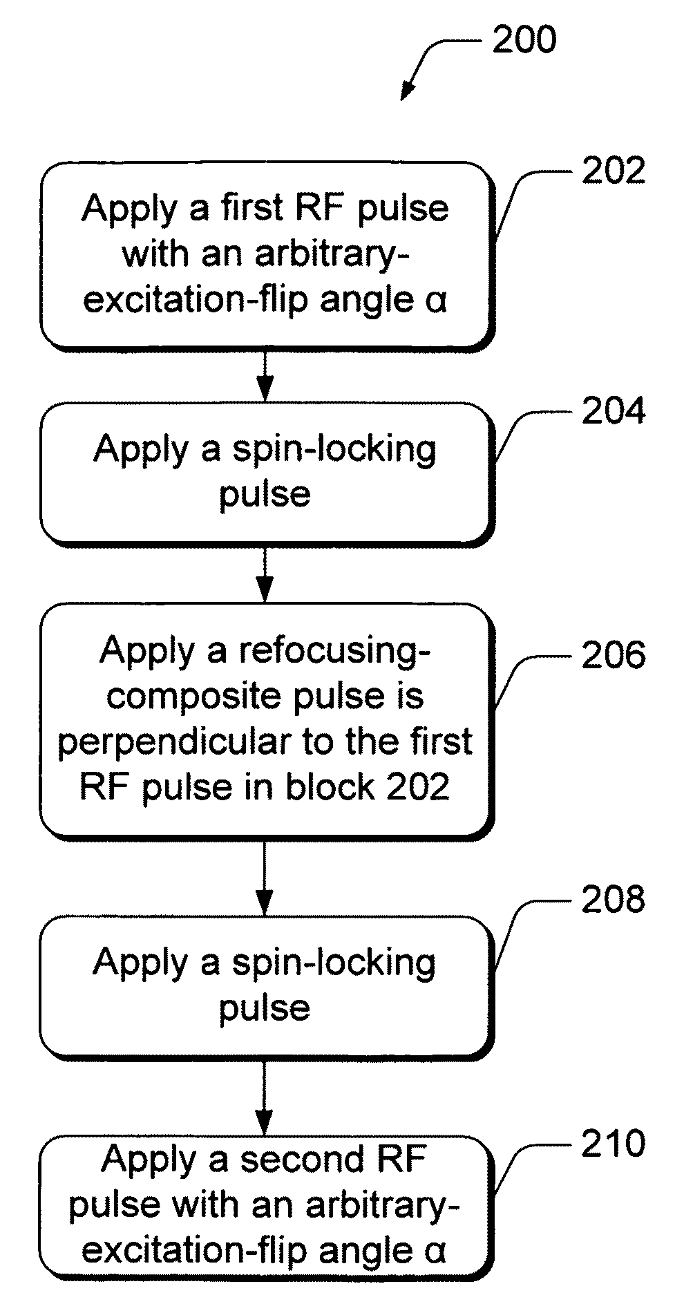
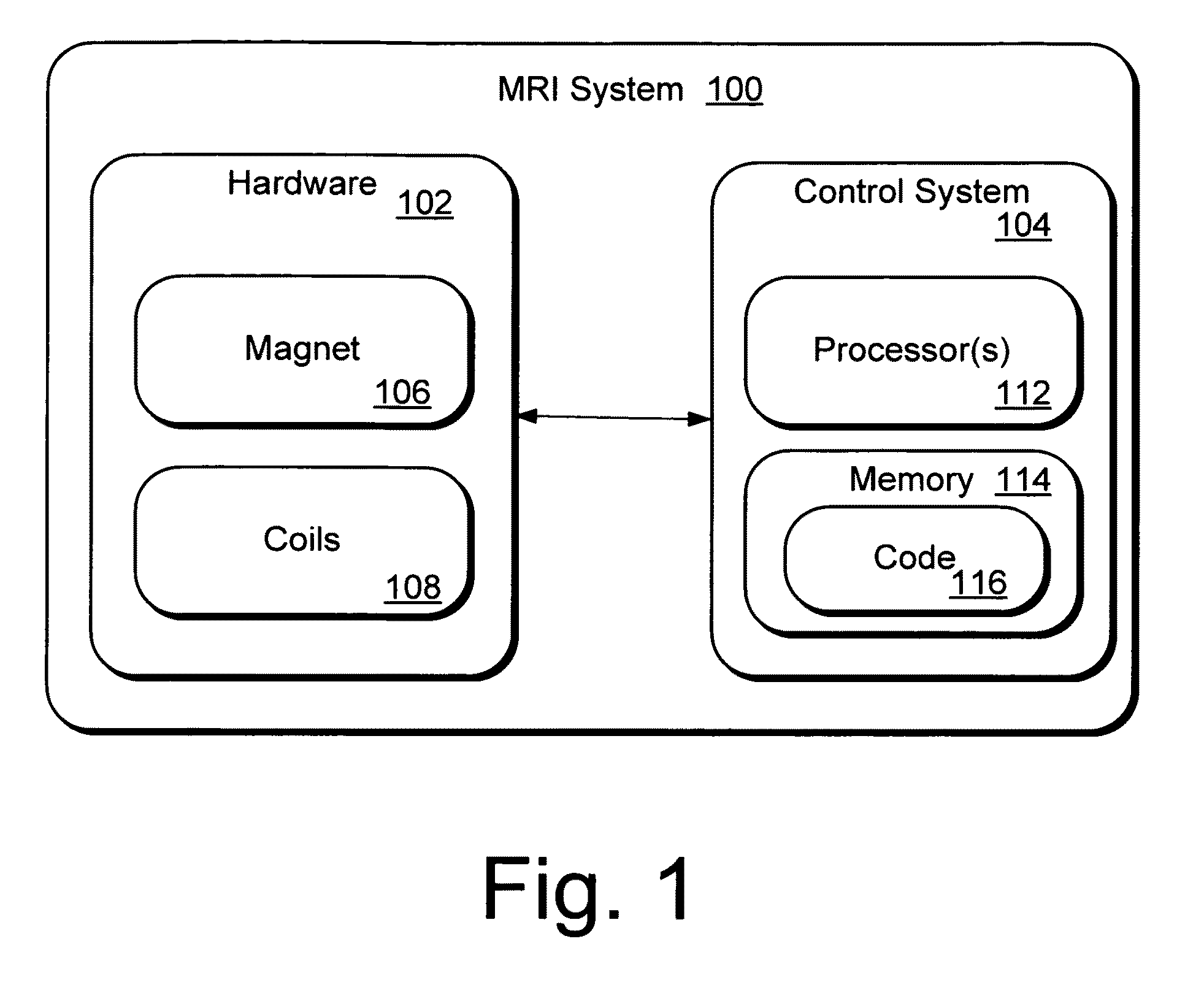
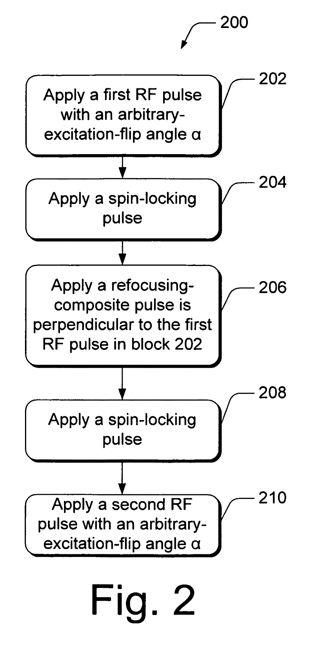
[0021]Described herein is an innovative MRI system and method able to simultaneously compensate for external-magnetic-field and radiofrequency magnetic-field inhomogeneities in an MRI system.

Definitions:

[0022]In describing the compensation methods, the following terminology will be used in accordance with the definitions set forth below.

[0023]As used herein, “α” refers to a radiofrequency pulse of arbitrary flip angle (_°=degrees).

[0024]As used herein, “apply” means to transmit or to deliver a radiofrequency pulse.

[0025]As used herein, “approximately 180°” refers to an angle sufficiently close to the 180°, but may be slightly less or more than 180°, as would be appreciated by those skilled in the relevant art.

[0026]As used herein, “B0” is an external-magnetic field, which is typically a Direct Current (zero frequency) superconducting field.

[0027]As used herein, “B1” is a radiofrequency-magnetic field delivered to create magnetic-resonance images.

[0028]As used herein, “cause” means t...


PUM


Abstract

Methods of, and systems for, simultaneously compensating for external-magnetic-field inhomogeneity as well as radiofrequency magnetic-field inhomogeneity in an MRI system. In one method embodiment, a pulse sequence is applied when the transmitter-reference frequency is delivered on resonance. The pulse sequence includes radiofrequency pulses which may be applied at arbitrary-excitation-flip angles that are not necessarily 90° degrees. The pulse sequence also includes spin-locking pulses applied in concert with a refocusing-composite pulse. In another method embodiment, a pulse sequence is applied when the transmitter-reference frequency is delivered off resonance. This off-resonance-pulse sequence includes radiofrequency pulses which may be applied at arbitrary-excitation-flip angles that are not necessarily 90° degrees. Sandwiched between the excitation-flip angles are at least two off-resonance-spin-lock pulses applied at an inverse phase and frequency from each other.

Description

CROSS-REFERENCE TO RELATED APPLICATIONS[0001]The present patent application claims benefit of U.S. Provisional Application Ser. No. 60 / 930,733 filed on 18 May 2007, which is incorporated herein by reference.STATEMENT OF GOVERNMENT INTEREST[0002]This work was supported by NIH grants R01AR045404 and R01AR051041, and performed at a NIH supported resource center NIH RR02305). The government may have certain rights in this invention.TECHNICAL FIELD[0003]The present invention relates to magnetic resonance imaging (MRI), and more particularly, to a system and method for minimizing imaging artifacts produced by MRI systems.BACKGROUND[0004]Magnetic Resonance Imaging (MRI) is an imaging technique based in part on the absorption and emission of energy in the radio frequency range. To obtain the necessary magnetic resonance (MR) images, a patient (or other target) is placed in a magnetic resonance scanner. The scanner provides a magnetic field that causes target atoms to align with the magnetic...

Claims


Application Information

Patent Timeline
IPC IPC(8): G01V3/00
CPCG01R33/56563G01R33/288G01R33/5659
Inventor WITSCHEY, WALTER R. T.BORTHAKUR, ARIELLIOT, MARK A.REDDY, RAVINDER
Owner THE TRUSTEES OF THE UNIV OF PENNSYLVANIA
Why Eureka
Try Eureka