Reticle
a technology of reticles and rings, applied in the field of rings, can solve the problems of not teaching reticles, circles can be difficult to use with great accuracy, etc., and achieve the effect of accurate trajectory compensation
- Summary
- Abstract
- Description
- Claims
- Application Information
AI Technical Summary
Benefits of technology
Problems solved by technology
Method used
Image
Examples
first embodiment
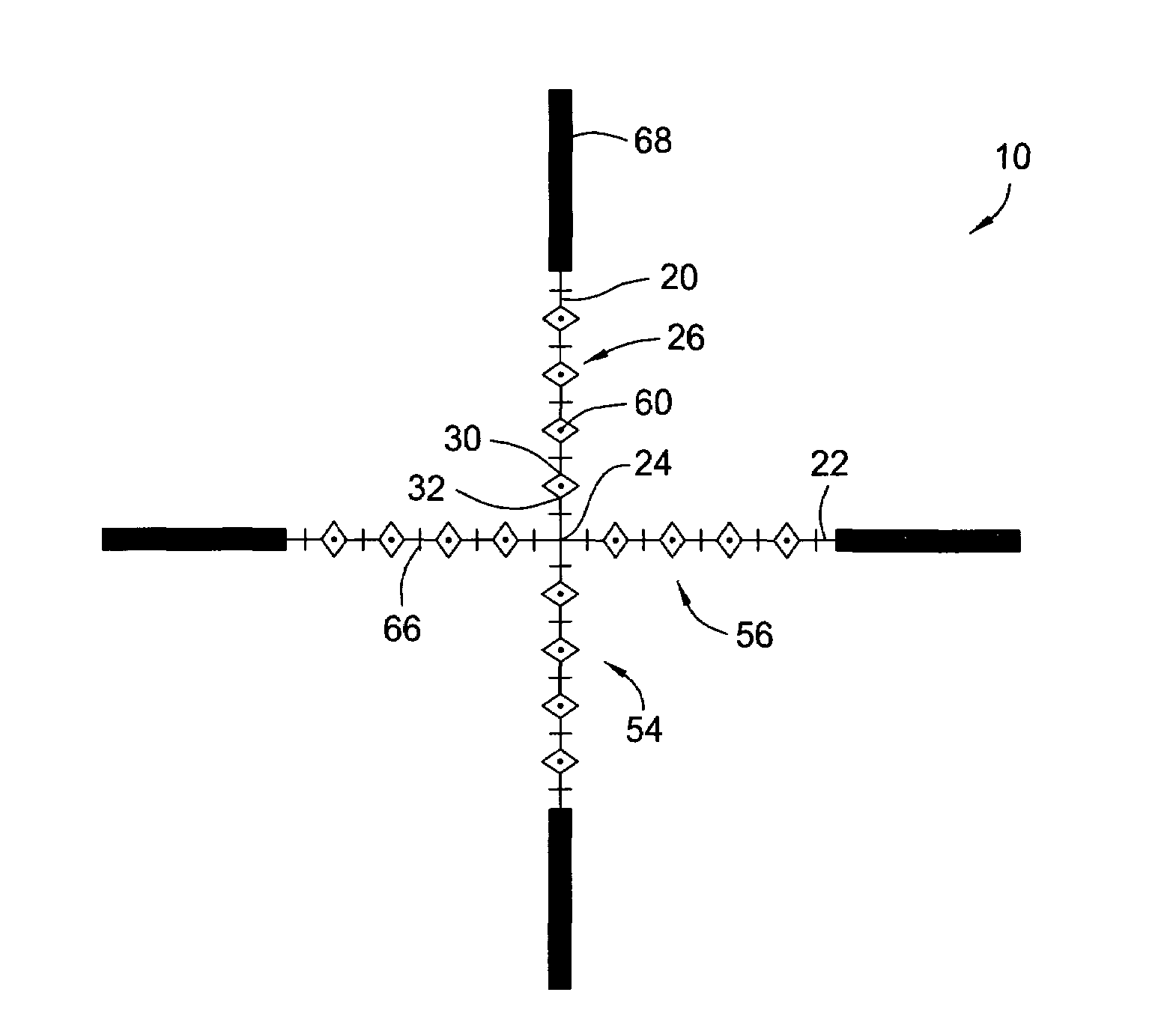
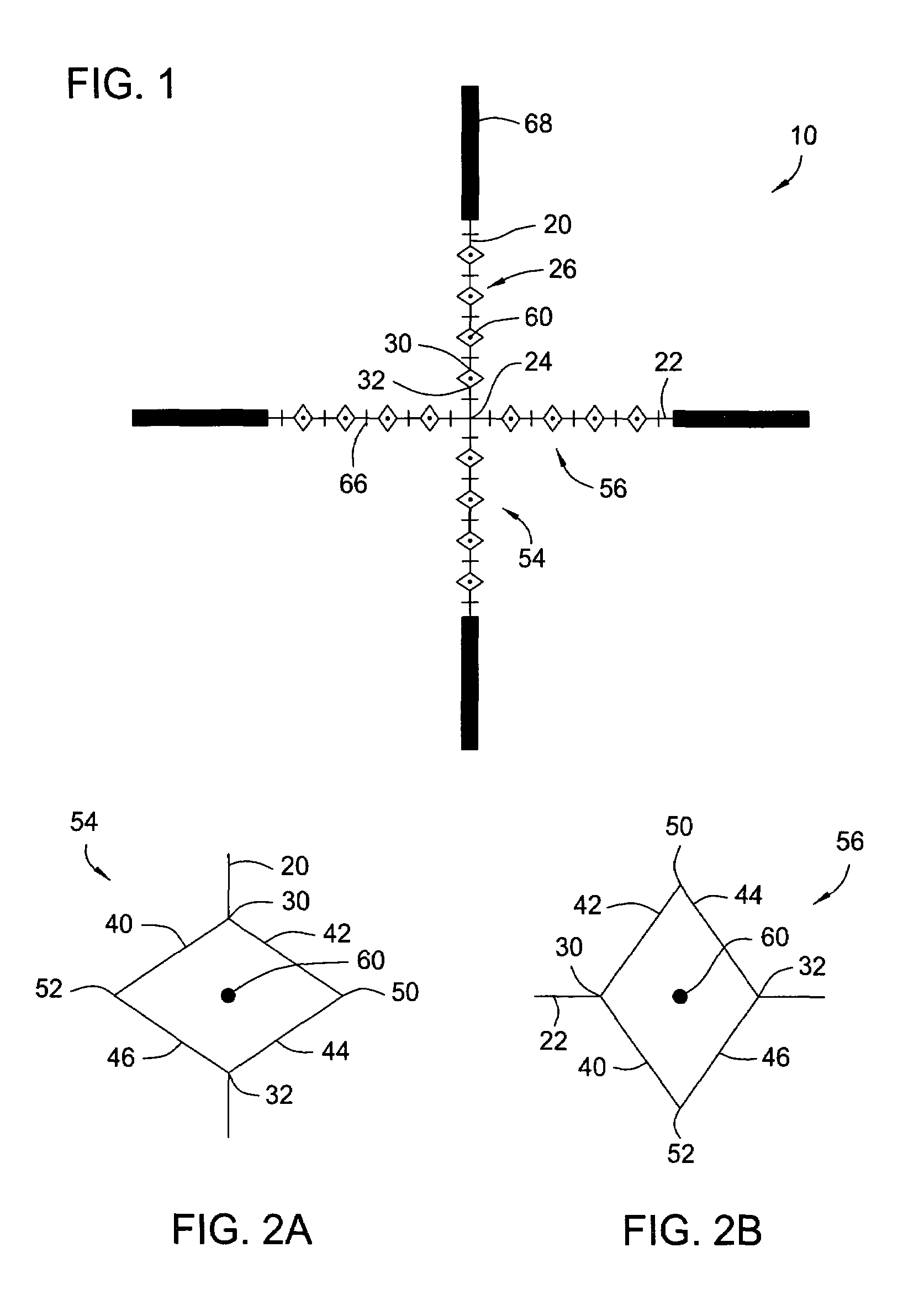
[0034]FIG. 1 is a top plan view of the reticle 10 according to the present invention. As shown in FIG. 1, the reticle 10 includes a vertical line 20, a horizontal line 22 intersecting the vertical line 20 at a center point 24, and a plurality of quadrilaterals 26. Each of the plurality of quadrilaterals 26 intersects either the vertical line 20 or the horizontal line 22 at two points to form first and second measuring points 30 and 32. Each of the first and second measuring points 30 and 32 is spaced a predetermined distance from the center point 24.
[0035]As shown in FIGS. 1, 2A, and 2B, each of the plurality of quadrilaterals 26 includes a first side 40, a second side 42, a third side 44, and a fourth side 46. The first and second sides 40 and 42 intersect to form the first measuring point 30; the third and fourth sides 44 and 46 intersect to form the second measuring point 32; the first and fourth sides 40 and 46 intersect to form a third measuring point 52; and the second and thi...
second embodiment
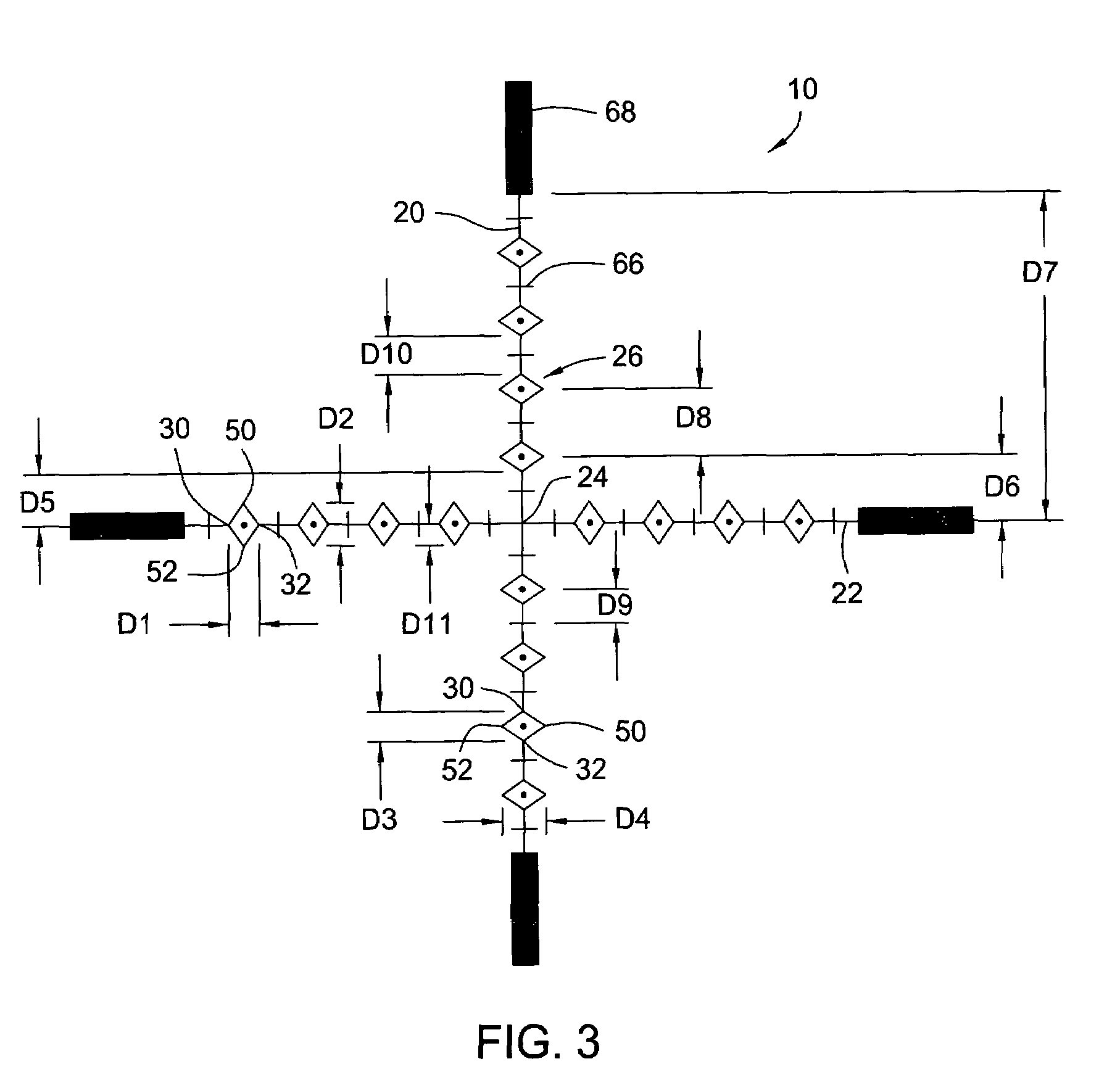
[0044]Of course, the measurements described in FIG. 3 may vary according to the specific requirements of the user. FIG. 4A is a top plan view of the reticle 10 of FIG. 1. As shown in FIG. 4A, the first distance D1 may be 0.25 MIL, while the second distance D2 is 0.20 MIL; and the third distance D3 may be 0.25 MIL, while the fourth distance D4 is 0.20 MIL. Other embodiments having alternative measurements are also considered possible, and should be considered within the scope of the claimed invention. Alternative examples include, but are not limited to, the following: 0.20×0.25, 0.25×0.20, 0.20×0.20, 0.25×0.25, 0.50×0.50, or any other measurement that a user might find useful.
third embodiment
[0045]FIG. 4B is a top plan view of the reticle 10 of FIG. 1. As shown in FIG. 4B, in this embodiment, the first distance D1 may be 0.25 MIL, while the second distance D2 is 0.20 MIL; and the third distance D3 may be 0.25 MIL, while the fourth distance D4 is 0.20 MIL. Obviously, those skilled in the art may device any arrangement of distances that may be useful to a user, and such alternative and / or equivalent arrangements should be considered within the scope of the claimed invention.
[0046]In the embodiments of FIGS. 4B and 5, each of the plurality of quadrilaterals 26 may further include a line 62 that connects the third and fourth measuring points 50 and 52. This line 62 may extend across the quadrilateral 26, as shown in FIG. 4B, or the line 62 may extend beyond the quadrilateral 26, as shown in FIG. 5. In the embodiment of FIG. 5, the line 62 extends a distance LD to extended points 64. These lines 62, and / or the extended points 64, provide additional points of reference for es...
PUM
 Abstract
Description
Claims
Application Information
 - R&D
- Intellectual Property
- Life Sciences
- Materials
- Tech Scout
- Unparalleled Data Quality
- Higher Quality Content
- 60% Fewer Hallucinations
Browse by: Latest US Patents, China's latest patents, Technical Efficacy Thesaurus, Application Domain, Technology Topic, Popular Technical Reports.
© 2025 PatSnap. All rights reserved.Legal|Privacy policy|Modern Slavery Act Transparency Statement|Sitemap|About US| Contact US: help@patsnap.com


