Power system module and method of fabricating the same

a technology of power system module and power system module, which is applied in the direction of printed circuit board receptacles, electrical apparatus construction details, electrical apparatus casings/cabinets/drawers, etc., can solve the problems of difficult to provide a power system module according to a customer's requirements, high cost of conventional power system modules, and large volume of control devices, etc., to achieve convenient and fast delivery, high integration, and convenient to meet customer specifications

Active Publication Date: 2010-04-27
SEMICON COMPONENTS IND LLC
View PDF15 Cites 31 Cited by
  • Summary
  • Abstract
  • Description
  • Claims
  • Application Information

AI Technical Summary

Benefits of technology

[0010]The present invention provides a power system module capable of easily fulfilling customers' specifications and being economically practical, and also capable of high integration.
[0011]The present invention also provides a manufacturing method of a power system module capable of easily fulfilling customers' specifications and being economically practical.

Problems solved by technology

First, it is difficult to provide a power system module according to a customer's requirements. This is because the control circuitry differs according to the type of product, and the power system module for each product is different. Accordingly, in order to meet a customer's requirements, a different power system module must be provided for each case, which is problematic from a manufacturing point of view.
Also, conventional power system modules are costly because a control device must be added to an already expensive power module package.
A control device can take up considerable volume, which increases the cost of the power system module and makes it difficult to employ complex control circuitry.
Additionally, conventional power system modules are difficult to highly integrate because a power device and a control device are both contained in a single package, resulting in low integration.

Method used


Image

  • Power system module and method of fabricating the same
  • Power system module and method of fabricating the same
  • Power system module and method of fabricating the same

Examples


Embodiment Construction

[0027]The present invention will now be described more fully with reference to the accompanying drawings, in which exemplary embodiments of the invention are shown. The invention may, however, be embodied in many different forms and should not be construed as being limited to the embodiments set forth herein; rather, these embodiments are provided so that this disclosure will fully convey the concept of the invention to those skilled in the art. In the drawings, the relative size of various components may be exaggerated for clarity.

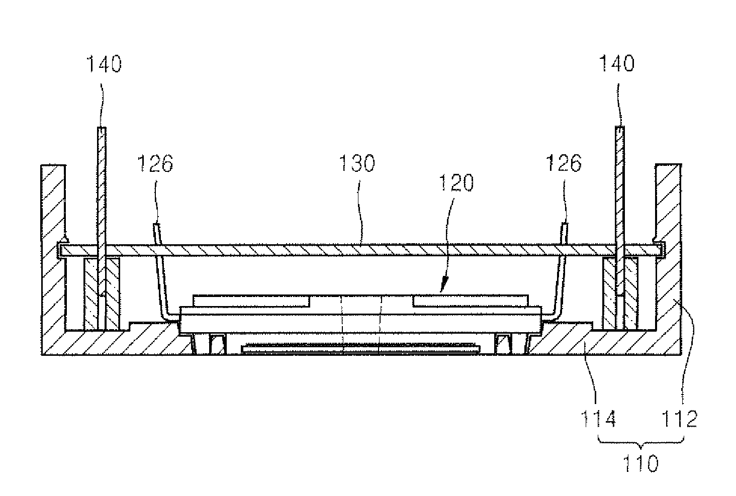
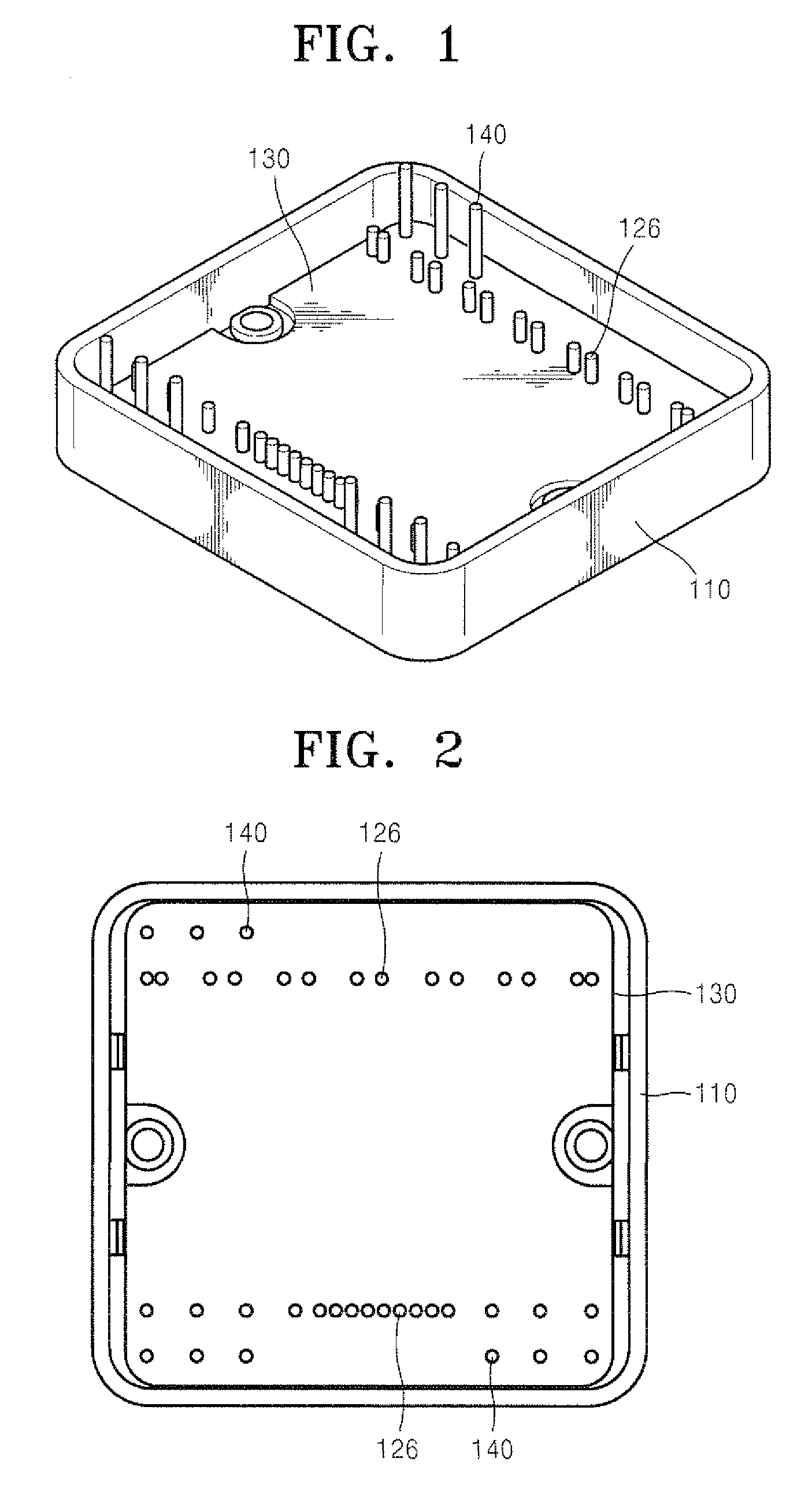
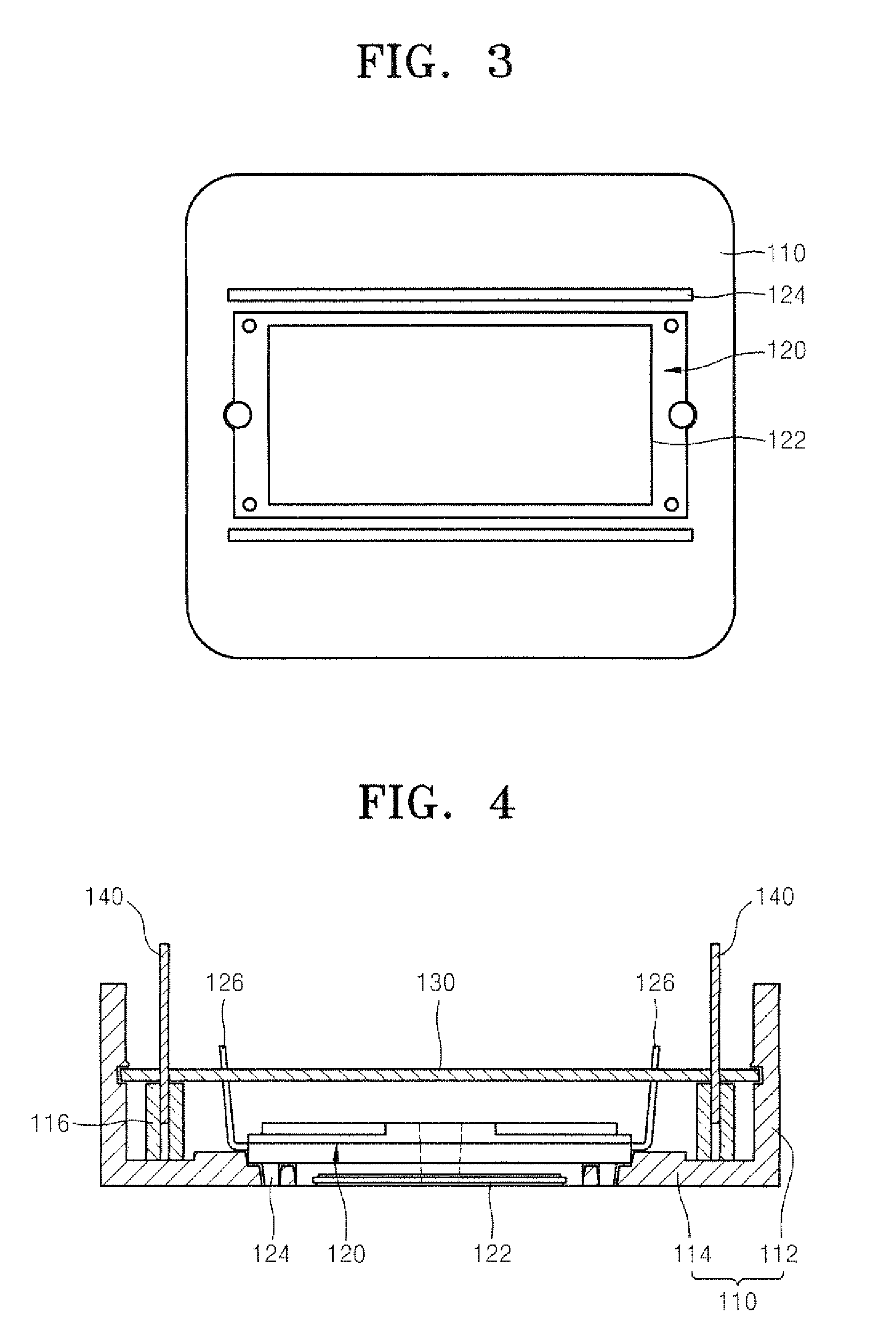
[0028]A power system module according to embodiments of the present invention may denote a system including a module with a power device and a module with a control device. That is, a power device and a control device may form the circuit of the power system. The power device may include a power MOSFET, a bipolar transistor, or an insulated gate bipolar transistor (IGBT), but is not limited to such inclusion.

[0029]FIGS. 1 through 4 illustrate a power syst...


PUM

PropertyMeasurementUnit
conductiveaaaaaaaaaa
electrical connectingaaaaaaaaaa
volumeaaaaaaaaaa

Abstract

Provided are a power system module allowing a user's requirements to be easily met, and having economic practicality and high integration, and a manufacturing method thereof. The power system module includes a plastic case, a molding type power module package, a control circuit board, and at least one external terminal. The plastic case defines a bottom and a side wall. The molding type power module package is fixed to the bottom of the plastic case and includes at least a power device therein. The control circuit board is fixed to the side wall of the plastic case, includes at least a control device mounted thereon which is electrically connected to the power module package. The external terminal protrudes to outside the plastic case and is electrically connected to the control circuit board.

Description

CROSS-REFERENCE TO RELATED PATENT APPLICATION[0001]This application claims the benefit of Korean Patent Application No. 10-2006-0035770, filed on Apr. 20, 2006, in the Korean Intellectual Property Office, the disclosure of which is incorporated herein in its entirety by reference.BACKGROUND OF THE INVENTION[0002]1. Field of the Invention[0003]The present invention relates to a semiconductor device, and more particularly, to a power system module including a power device and a control device, and a manufacturing method of the power system module.[0004]2. Description of the Related Art[0005]Conventional power system modules are manufactured with a power device integrally packaged with a control device. Power devices include MOSFETs, bipolar transistors, and insulated gate bipolar transistors (IGBT). Control devices have a wide variety of control circuits depending on the type of product. An example of a power system module with a power device and a control device stacked and molded on...

Claims


Application Information

Patent Timeline
Patent Type & Authority Patents(United States)
IPC IPC(8): H05K5/00
CPCH01L25/165H02M7/003H05K7/1432Y10T29/49002H01L2924/0002H01L2924/00H05K7/14322H01L25/10
Inventor LEE, KEUN-HYUKLIM, SEUNG-WONPAEK, SEUNG-HANPARK, SUNG-MIN
Owner SEMICON COMPONENTS IND LLC
Why Eureka
Try Eureka