Low power radio device for providing access to aircraft communications (or other specialized communications) to the general public via commercial radio bands and receivers

Inactive Publication Date: 2010-04-27
MOORE MICHAEL DAVID
37 Cites 2 Cited by

AI-Extracted Technical Summary

Problems solved by technology

The inability to easily listen to such communications is a roadblock to participation in General Aviation and presents a barrier, perceived and unperceived, that aviation in general is expensive and exclusive.
Receiving followed by retransmitting has taken a myriad of forms in the prior art, but none combine low power transmitter operation, integral station identification messages, and a fixed installation such as at an airport.
(1999) is concerned with rebroadcast of portable (cellular) telephone audio to an automobile's AM/FM radio and thus is presumably low power but is implicitly confined to the region of the interior of a vehicle, since it is obv...

Method used

[0075]In the case of an AM version of the invention, antenna 21 is matched to the low power transmitter 20 with an appropriately sized loading coil, and incorporates conventional antenna enhancements 26 for increased radiation efficiency. For AM transmissions, enhancements 26 can be a capacitive top hat. For FM transmissions, enhancements 26 can also be applied to achieve the efficiency improvements well known in the literature, such a vertical dipole, ¼ wave, ⅝ wave collinear, log periodic, and other configurations.
[0087]FIG. 4 shows an elevation view of an outdoor installation which maximizes transmission range for a single instance of this embodiment, since no interposing structure 34 is present to attenuate the low power transmitter 20 signal. Components 11-20 of FIG. 1 are placed in a weatherproof outdoor enclosure 22b. The enclosure 22b is mechanically supported by ground rod 23 which is securely driven into the earth 24 and thus rod 23 also serves as the electrical ground connection. This installation method allows minimization of the grounding distance for the transmitter 20 circuitry and maximizes the possible length of antenna 21.
[0099]d) Because the embodiments can be indoor, outdoor, and indoor/outdoor embodiments, the limitation on low power broadcasting (LPAM, low power AM, and LPFM, low power FM) can be overcome by positioning the transmitting portion of the invention outdoors to maximize range. These embodiments enable the maximum antenna length and maximum ground length allowed by the FCC, and can be positioned adjacent to viewing areas (agai...

Abstract

One embodiment of a radio device, in which a specialized receiver and antenna (10 and 11), an input mechanism (14), a storage area (12), a timer/multiplexer (16) and timer/multiplexer switch (17), control signals (13, 15, 18, and 19), low power transmitter (20) and low power transmitter antenna (21), under FCC Part 15 low power transmitter rules, provide aircraft communications to the general public on commercial AM and FM bands.

Application Domain

Frequency-division multiplex detailsActive radio relay systems +6

Technology Topic

EngineeringMuxponder +6

Image

  • Low power radio device for providing access to aircraft communications (or other specialized communications) to the general public via commercial radio bands and receivers
  • Low power radio device for providing access to aircraft communications (or other specialized communications) to the general public via commercial radio bands and receivers
  • Low power radio device for providing access to aircraft communications (or other specialized communications) to the general public via commercial radio bands and receivers

Examples

  • Experimental program(1)

Example

Reference Numerals
[0034] 10 receiving antenna for specialized transmissions [0035] 11 specialized receiver [0036] 12 storage area [0037] 13 receiver control signal(s) [0038] 14 input mechanism for station identification, audio, data, configuration, and control [0039] 15 timer/multiplexer output signal(s) [0040] 16 timer/multiplexer [0041] 17 multiplexing switch [0042] 18 timer/multiplexer data and control signal(s) [0043] 19 transmitter control/data signals [0044] 20 low power transmitter [0045] 21 transmitter antenna [0046] 22a indoor embodiment [0047] 22a′ range of embodiment 22a [0048] 22b outdoor embodiment [0049] 22b′ range of embodiment 22b [0050] 22c indoor embodiment of reference numerals 11-18 [0051] 22c′ range of embodiment 22c [0052] 22d output embodiment of reference numeral 20 [0053] 22d′ range of embodiment 22d [0054] 23 combination electrical ground and support rod [0055] 24 earth (terra firma) [0056] 25 conventional power connection [0057] 26 conventional antenna enhancements [0058] 27 wall of structure [0059] 28 window of structure [0060] 29 conventional wireless frequency indoor antenna [0061] 30 conventional wireless frequency outdoor antenna [0062] 31 elevated, indoor flat surface [0063] 32 signage for advertising radio device [0064] 33 support for signage [0065] 34 building or structure [0066] 35 perimeter fence [0067] 36 spectator/user and automobile [0068] 37 spectator/user and automobile
DETAILED DESCRIPTION—FIGS 1-3—PREFERRED EMBODIMENT
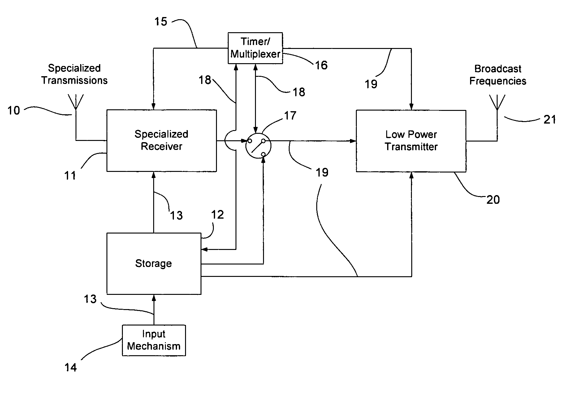
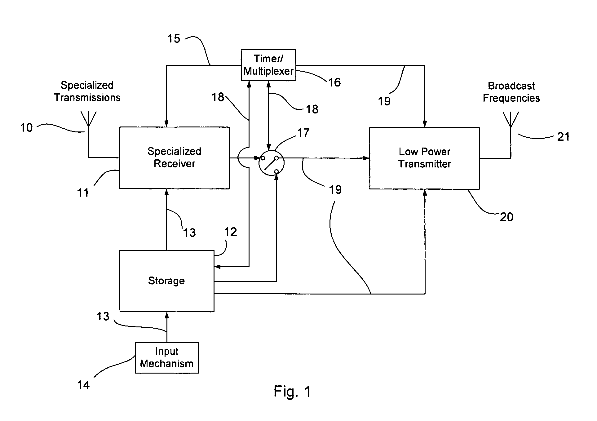
[0069]In FIG. 1, receiving antenna 10 collects the specialized frequencies of interest and is connected to receiver 11. Receiver 11 can be digital, analog, or a combination of analog and digital; microprocessor based, software based, or soft radio based. Internal details of receiver 11 are well known to anyone familiar with the state of the art in radio reception. Receiver 11 converts signals from receiving antenna 10 into an intermediate form, either the actual representation in terms of audio, or an AM or FM signal that is suitable for immediate retransmission. The output of receiver 11 is connected to timer/multiplexer switch 17, and receiver 11 is connected via control signals 13, 15 to timer/multiplexer 16 and input mechanism 14. Timer/multiplexer 16 may be a digital machine such as a microprocessor, micro computer, computer, or simply an electronic RC (resistive-capacitive) based timing and switching device.
[0070]Input mechanism 14 is connected to and supplies data to storage area 12 via control and data signals 13. Input mechanism 14 is also connected to receiver 11 through storage 12, to timer/multiplexer 16, transmitter 20, and supplies data, configuration parameters, and control to these components also.
[0071]Input mechanism 14 may consist of a personal computer, PDA (personal digital assistant), wired or wireless link, cell phone, analog channel, digital channel, microphone, or any combination of the preceding. The data in storage 12 may be used by the low power (less than 100 mW) transmitter 20, or be used to configure specific parameters (such as frequency of operation or time interval) of the receiver 11, low power transmitter 20, or timer/multiplexer 16. Timer/multiplexer 16 is connected to and controls multiplexing switch 17 that multiplexes the signals from receiver 11 and the storage 12 using connected control signals 18. Control signals 13, 15, 18, and 19 can be used to sequence operation of receiver 11, low power transmitter 20, input mechanism 14, or to turn on or off any of these connected components.
[0072]Receiver 11 is connected to low power transmitter 20 via control and data signals 19. Signals 19 may be wired or wireless, analog or digital data. After a selection by timer/multiplexer 16, switch 17 has been positioned accordingly, and the selected signals 19 are sent to low power transmitter 20. Conventional low power transmitter 20 modulates (in the case of actual audio) and/or amplifies (in the case of an intermediate signal from receiver 11) the input data signals 19 to convert to LPAM (Low Power Amplitude Modulation) or LPFM (Low Power Frequency Modulation) levels. Antenna 21, connected to low power transmitter 20, radiates this signal to the user listening with his/her commercial band radio.
[0073]An indoor embodiment is shown in FIG. 2 housed in an enclosure 22a and placed in a suitable location such as on a flat surface 31 near wall 27 and window 28, with antenna 11 for receiving specialized signals and antenna 21 for transmitting on commercial bands positioned so that antenna 21 radiates outside structure 27, 34. The indoor embodiment is connected to power 25, consisting of conventional power sources such as alternating current (AC), direct current (DC) or batteries, solar cells, or any other sufficient power source known to the state of the art.
[0074]FIG. 3 shows an aerial view of the installation of an indoor embodiment. The low power transmitter of the indoor embodiment 22a has range 22a′, and is installed inside structure or building 34. Spectators are apprised of the existence of the embodiment with signage 32 on signage support 33. Users 36 within range are able to listen to aircraft communications (or other specialized communications) on the side of perimeter fence or barrier 35. Users 37 out of range of embodiment 22a are unable to receive the signals from low power transmitter 20, the useful range of such transmitters being 30-300 m (100-1000 ft).
[0075]In the case of an AM version of the invention, antenna 21 is matched to the low power transmitter 20 with an appropriately sized loading coil, and incorporates conventional antenna enhancements 26 for increased radiation efficiency. For AM transmissions, enhancements 26 can be a capacitive top hat. For FM transmissions, enhancements 26 can also be applied to achieve the efficiency improvements well known in the literature, such a vertical dipole, ¼ wave, ⅝ wave collinear, log periodic, and other configurations.
Operation
[0076]The preferred embodiment is first set up by an operating person or persons (the operator), usually a Fixed Base Operator (FBO) at an airport. The operator first determines commercial frequency(ies) fT in the geographical area that are not already being used by local broadcast stations. These frequencies can be AM, FM or both. Determining unused or distantly used commercial frequencies adheres to the FCC Part 15 operating rules for low power transmitters.
[0077]The operator installs the invention indoors 22a (FIG. 2), outdoors 22b (FIG. 4), or with a combination of indoors and outdoors 22c and 22d (FIG. 6), and hangs or posts 33 signage 32 (FIG. 2) indicating the presence of the embodiment and the commercial transmission frequency(ies) fT being used.
[0078]The operator then turns the embodiment on using a switch or data supplied to timer/multiplexer 16 via input mechanism 14 in FIG. 1.
[0079]The operator next stores the specialized (aircraft communication) receiving frequencies fR to be multiplexed onto commercial band transmission frequencies fT using input mechanism 14 of FIG. 1. The operator assigns each of these frequencies fR a priority, from highest to lowest, or lowest to the highest employing input mechanism 14. Using these priorities and time, transmissions on the most important frequencies fR will be chosen over lesser priority frequencies by timer/multiplexer 16.
[0080]For example, timer/multiplexer 16 may thus prioritize frequencies from receiver 11 so a higher, more important frequency is selected unless it is not in use. In this case, the next lower priority signal is selected by timer/multiplexer 16 and sent to switch 17.
[0081]Using input mechanism 14, the operator then records station identification, public service, advertisement, or other audio or data, and this data is placed in storage 13.
[0082]During operation, timer/multiplexer 16 cycles through the aircraft frequencies of interest according to priority, order, time, or other criteria. Upon finding an active frequency from receiver 11, timer/multiplexer 16 positions switch 17 to pass the appropriate signal (either audio or directly transmissible modulated signal) to transmitter 20, using control signals 19. Receiver 11 and transmitter 20 may either or both contain appropriate and legal means for boosting the signals into and out of each. Antenna 21 then radiates the multiplexed aircraft (or other specialized) communications to the user (listener).
[0083]At appropriate times, timer/multiplexer 16 changes switch 17 to the proper position for a recorded station identification (identifying low power transmitter 20) message and retrieves this message from storage 12. The full or partial contents of storage 12 are transmitted as dictated by the operation of timer/multiplexer 16.
[0084]At specific or random intervals, timer/multiplexer 16 selects public service, advertising, or other data stored in storage area 12. In the case of aircraft communications, timer/multiplexer also periodically selects the Automated Weather Observation System (AWOS) signal (or similar signal) from receiver 11.
[0085]Note that if no channel being scanned is active, the timer/multiplexer may either continue to transmit the AM or FM carrier (no modulated audio) or may disable transmitter 20 to economize on power. At times entered by the operator via input mechanism 14, timer/multiplexer may also turn some (or all) of the components in FIG. 1 on or off to match a day/night or other time cycle.
[0086]In FIG. 3, users or spectators wishing to listen to the invention to hear the aircraft communications arrive at parking 36, 37 or building 34 with their commercial band receivers, or simply turn the car radio on. The user then tunes to the commercial frequency fT indicated on signage 32, and hears the aircraft communications on frequencies fR (multiplexed using the assigned priorities), as well as periodically or randomly any messages contained in storage 12.
Alternative Embodiments
[0087]FIG. 4 shows an elevation view of an outdoor installation which maximizes transmission range for a single instance of this embodiment, since no interposing structure 34 is present to attenuate the low power transmitter 20 signal. Components 11-20 of FIG. 1 are placed in a weatherproof outdoor enclosure 22b. The enclosure 22b is mechanically supported by ground rod 23 which is securely driven into the earth 24 and thus rod 23 also serves as the electrical ground connection. This installation method allows minimization of the grounding distance for the transmitter 20 circuitry and maximizes the possible length of antenna 21.
[0088]This outdoors embodiment thus allows maximum transmitted power and best radiation efficiency of low power transmitter 20 under the FCC Part 15 regulations that limit AM versions of the embodiment to 3 m of combined ground and antenna length and FM versions of the embodiment by actual radiated field strength measurements, since no interposing building structure exists that will attenuate the transmitted signal.
[0089]Conventional electrical power 25 (not shown) is supplied to the outdoor installation via AC, DC, battery, or an attached solar cell, the specific supply mechanism being the best suited for the specific installation.
[0090]FIG. 5 shows an aerial view of the outdoor installation where a plurality of embodiments 22b having overlapping ranges 22b′. Spectators and users arrive at parking 36, 37 or structure 34 and tune to the commercial frequencies shown on signage 32, positioned on or near perimeter fence 35.
[0091]FIG. 6 shows the indoor/outdoor installation for used for covering the most area with multiple copies of this embodiment. The components 11-18 of FIG. 1 are contained indoors in enclosure 22c. Enclosure 22d contains low power transmitter 20 and mounts low power transmitter antenna 21 of FIG. 1.
[0092]In the embodiment of FIG. 6, control and data signals 19 of FIG. 1 are now wireless signals. Because signals 19 are now wireless, the range between receiver embodiment 22c and any transmitter embodiment 22d can be upwards of miles. A plurality of low power AM or FM transmitters 22d can now be placed at will anywhere within the range of signals 18, and thus AM or FM coverage area is extremely large, even while still adhering to the FCC Part 15 low power transmitter regulations.
[0093]Indoor embodiment 22c sits on a flat surface, next to the window 28 of building or structure 27. Antenna 10 collects specialized (or aircraft) frequencies. Conventional wireless data antenna 29 transmits high frequency (such as in the 400 MHz or 900 MHz bands) control and data signals 18 to conventional wireless data receiving antenna 30 on transmitter embodiment 22d. Low power transmitter embodiment 22d then converts signals 18 and retransmits these signals on commercial AM or FM bands using antenna 21. A plurality of embodiments 22d with range 22d′ are now placed within range 22c′ of indoor embodiment 22c, and users and spectators positioned at 34, 36 and 37 have access to the low power transmitter 22d signals.
Operation
[0094]After a differing installation of an outdoor embodiment (FIG. 4) or indoor/outdoor embodiment (FIG. 6), the operation of these alternative embodiments as experienced by the operator and by the user is identical to the operation of the preferred embodiment of the FIGS. 1-3.
Advantages
[0095]From the prior description, numerous advantages of the described embodiments are evident:
[0096]a) Because the embodiments transmit on the commercial AM and FM bands, anyone with a portable, car, or personal radio can access and listen to specialized communications which normally are unavailable to listeners without specialized and expensive receivers.
[0097]b) Because the ability to receive specialized communications on common broadcast frequencies is immediately available and can be used spontaneously (spur of the moment desire to listen), barriers to participation (here in reference to aircraft communications) are removed which can generate interest and spur future participation in the activity (such as General Aviation).
[0098]c) Because the embodiments adhere to low power (<100 mW) transmission requirements under the FCC Part 15 low power rules, it does not need a costly station license.
[0099]d) Because the embodiments can be indoor, outdoor, and indoor/outdoor embodiments, the limitation on low power broadcasting (LPAM, low power AM, and LPFM, low power FM) can be overcome by positioning the transmitting portion of the invention outdoors to maximize range. These embodiments enable the maximum antenna length and maximum ground length allowed by the FCC, and can be positioned adjacent to viewing areas (again, such as next to a parking area with view of aircraft taxiway and runway operations).
[0100]e) Because the limitations on LPAM and LPFM can be overcome by positioning embodiments at desired locations, multiple instances of the invention can be placed at intervals to allow transmission coverage that is much greater than what is allowed under FCC Part 15 low power rules, while maintaining a legal transmit output power for each instance of the invention.
[0101]f) Because the embodiments can be envisioned in outdoor, indoor/outdoor, and indoor embodiments, the receiving portion of the embodiments can be placed either completely singly outside any structure, can accompany each transmitter in each instance of multiple copies of the invention, or can be singly installed indoors and communicate with one or more instances of low power transmitters placed outdoors to achieve the aforementioned increased coverage area and the decreased cost of only a single specialized receiver.
[0102]All of the above features lend themselves to installations of the embodiments that are both capable of covering a large area to serve a listening audience the best possible, as well as achieve low cost of the installation and operation.
Conclusion, Ramifications, and Scope
[0103]Accordingly, the reader will see that each of the embodiments provides users access to aircraft (or other specialized communications) without having to purchase specialized receivers or be aware of specialized frequencies. Because the embodiments incorporate low power (FCC Part 15) transmitters, the cost of providing such access is quite nominal and no expensive station licenses are required. Because of the aforementioned embodiments, the range limitations caused by power limitations and interposing structures can be overcome by outdoor or indoor/outdoor embodiments, each of these example embodiments having specific and distinct advantages of cost, ease of installation, coverage overlap, and number of installations.
[0104]Furthermore, in the case of aircraft communications, the embodiments have the additional advantages:
[0105]barriers to learning the language of air traffic control are removed as anyone with a car or personal radio can observe air traffic and correlate the sometimes abstruse and terse language with the viewed aircraft operations and actions;
[0106]the removal of this barrier encourages familiarity with air traffic control language, which allows pilots and prospective pilots a head start on learning the communications necessary for safe aircraft operations;
[0107]perceived barriers in radio communications due to trepidations over verbal mistakes and mis-spoken intentions are removed, as examples of such mistakes and remedies for such mistakes will become apparent through listening, and those uncomfortable with such radio communications will see others making and overcoming verbal mistakes;
[0108]persons familiar with student pilots and pilots will be able to listen for their relatives or friends and participate in and enjoy events like first solos, check rides, and arrivals and departures;
[0109]the perception of General Aviation as exclusive, expensive, and hard to reach is mitigated to listeners and spectators.
[0110]Although the prior description contains many specifications, it should not be construed as to limit the scope of any embodiment, but is intended as simply an illustration of possible or presently preferred embodiments.
[0111]For example, several specialized receivers 11 may be needed because of signal variations over a certain area or the desire to segregate specific receiving frequencies to specific listening areas. Low power transmitters 20 may also operate at several frequencies, based on available open bandwidth in the commercial spectrum and the desire to provide both AM and FM transmissions simultaneously.
[0112]Additionally, for indoor embodiments antennas 10 and 21 may be positioned, affixed, held, or otherwise located on or next to window 28 such that the signal received by antenna10 and the signal radiated from antenna 21 are maximized.
[0113]For indoor/outdoor embodiments, the method of communication between the specialized receiver 22c and low power transmitter 22d may be different for different installations, portions of installations, or for other reasons. The method of communication between specialized receiver 22c and low power transmitter 22d illustrated as electronic (either wired or wireless), but also may be photonic (optical), digital, analog, or any other type of communications contemplated by the industry. Also in the case of an indoor/outdoor embodiment, conventional power 25 to the receiving and transmitting portions of the invention may be separate and distinct.
[0114]Thus the scope of the embodiment should be determined by the appended claims and their legal equivalents, rather than by the examples given.

PUM

no PUM

Description & Claims & Application Information

We can also present the details of the Description, Claims and Application information to help users get a comprehensive understanding of the technical details of the patent, such as background art, summary of invention, brief description of drawings, description of embodiments, and other original content. On the other hand, users can also determine the specific scope of protection of the technology through the list of claims; as well as understand the changes in the life cycle of the technology with the presentation of the patent timeline. Login to view more.
Why Eureka
Try Eureka