Mechanical seal assembly

a mechanical seal and assembly technology, applied in the field of mechanical seals, can solve the problems of difficulty often encountered, rotary seal face of prior art mechanical seal assembly designs has a tendency to pop out after being inserted, and posed several problems in previous split mechanical seal designs, so as to facilitate the installation facilitate the insertion of rotary seal rings

Active Publication Date: 2010-05-04
A W CHESTERTON
View PDF23 Cites 41 Cited by
  • Summary
  • Abstract
  • Description
  • Claims
  • Application Information

AI Technical Summary

Benefits of technology

[0009]The present invention provides an improved mechanical seal assembly for sealing a component, such as a pump or any rotating equipment. The mechanical seal assembly may include a rotary seal ring connected to moving components of the equipment being sealed, a stationary seal ring that creates a seal against the rotary seal ring and is connected to stationary components of the equipment being sealed, and associated assembly components. The improved mechanical seal assembly may include a rotary seal ring holder clamped around the shaft for holding the rotary seal ring in a selected position and configuration. The rotary seal ring holder is configured to facilitate installation of the rotary seal ring into the rotary seal ring holder and maintain the perpendicularity of the rotary seal face to the shaft being sealed. The rotary seal ring may include a detent for capturing and aligning a sealing element, such as an O-ring, for sealing against a radially outer surface of the rotary seal ring. A double angled lead-in facilitates insertion of the rotary seal ring and O-ring into the rotary seal ring holder.
[0010]The improved mechanical seal assembly may include a gland assembly having interacting, mating halves to facilitate engagement of the gland halves and reduce or prevent sliding of the gland halves relative to each other when forces from the bolts, the equipment housing, the gasket support and / or other sources are applied to the gland assembly.

Problems solved by technology

Previous split mechanical seal designs posed several problems.
A first problem with prior split mechanical seal designs relates to the insertion of the rotary seal ring into the holder assembly that is clamped around the shaft.
The rotary seal face must be pushed into a tight space inside the clamped holder, and some difficulty may often be encountered.
In addition, since the O-ring tends to grab the seal ring and inhibits sliding, the rotary seal face of prior art mechanical seal assembly designs has a tendency to “pop-out” after being inserted.
Further, the movement of the O-ring when installed can result in the O-ring being disposed in an angled position, rather than a more preferred vertical position relative to the rotary seal ring.
From the angled position, the installer would be required to move the O-ring back to the original position, which is difficult.
If significant enough, this can result in shortened seal life.
Another problem experienced with prior split mechanical seal designs occurs when excessive torque is applied to the gland bolts while tightening the seal gland to the pump or other equipment housing.
This problem is most severe when only two gland bolts are used.
If this were done, however, when four bolts are used, the other two bolts would be located right at the split, which is undesirable.
Therefore when only two bolts are used for the gland assembly, the loading on the gland halves is not symmetrical or even with respect to the split plane.
The alignment pins are quite small in relation to the forces applied, and therefore cannot ensure that the gland halves will not slide against each other thereby distorting the alignment pin and the gland halves.
The result is twofold: first there is a reduction in sealing ability of the gaskets between the gland halves, and second, there is an out-of-round twisting of the gland assembly which creates sealing problems with the stationary seal ring.

Method used


Image

  • Mechanical seal assembly
  • Mechanical seal assembly
  • Mechanical seal assembly

Examples


Embodiment Construction

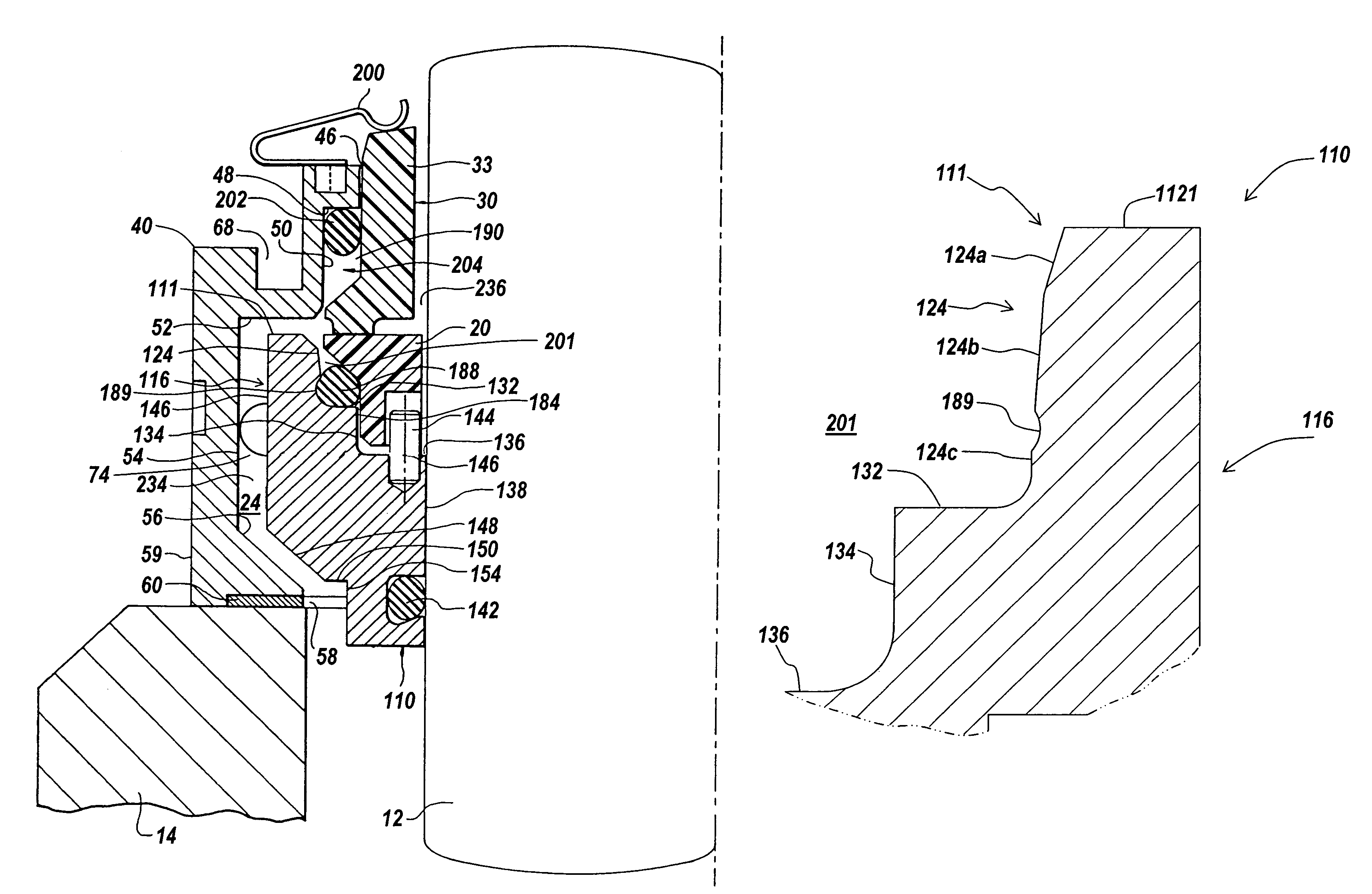
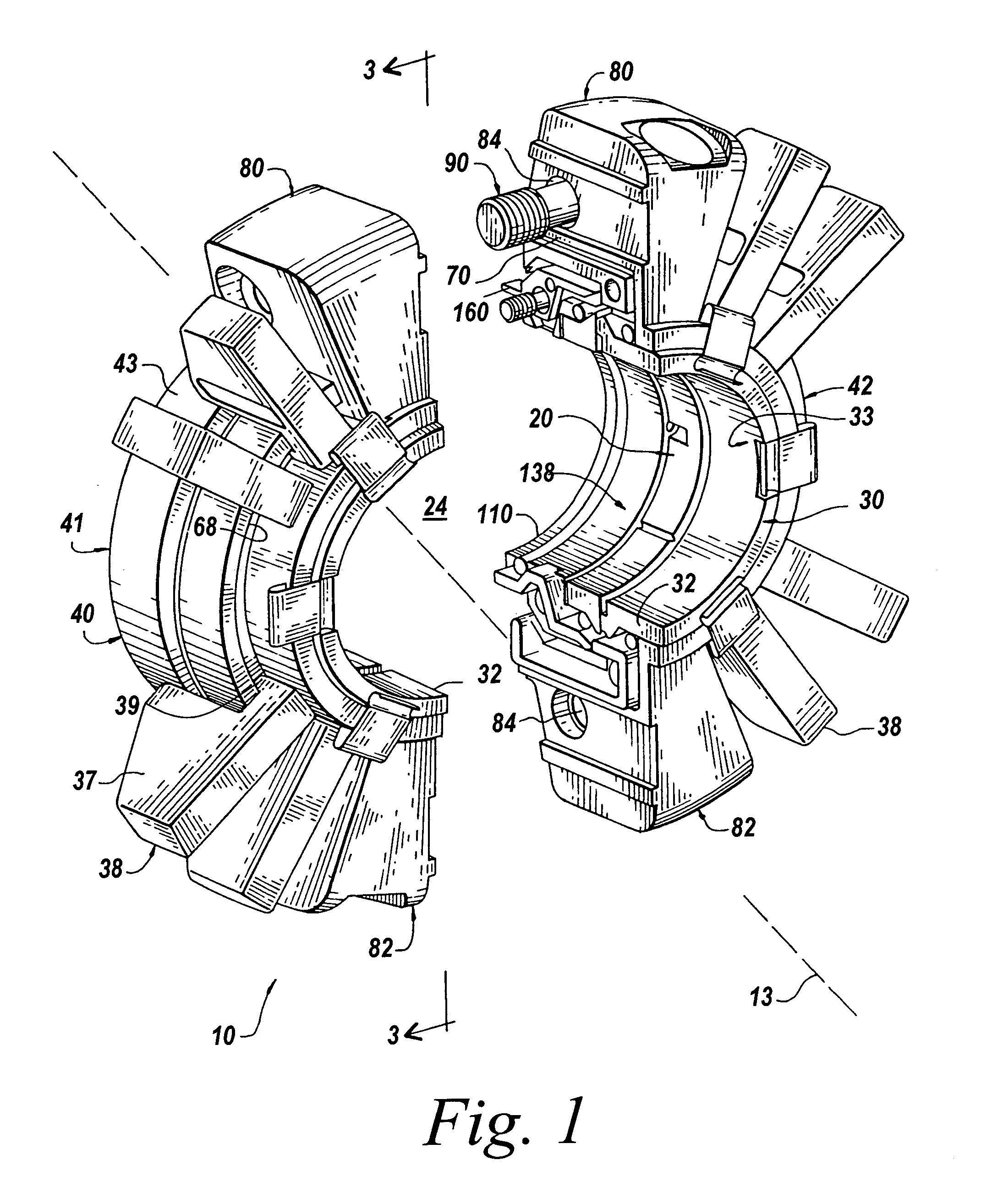
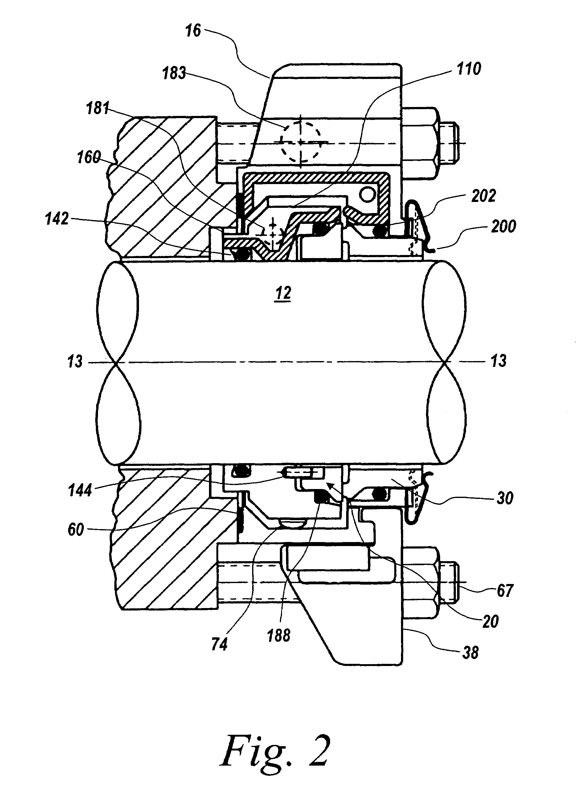
[0036]The present invention provides a mechanical seal assembly for providing sealing on a rotating shaft or other suitable device. The invention will be described below relative to illustrated embodiments. Those skilled in the art will appreciate that the present invention may be implemented in a number of different applications and embodiments and is not specifically limited in its application to the particular embodiment depicted herein.

[0037]The terms “seal assembly” and “sealing assembly” as used herein are intended to include various types of sealing assemblies, including single seals, split seals, concentric seals, spiral seals, and other known seal and sealing assembly types and configurations.

[0038]The term “shaft” is intended to refer to any suitable device in a mechanical system to which a seal can be mounted and includes shafts, rods and other known devices.

[0039]The terms “axial” and “axially” used herein refer to a direction generally parallel to the axis of a shaft. T...


PUM


Abstract

A split mechanical composite seal assembly for providing a seal between a rotating shaft and a static surface. The split mechanical composite seal assembly includes first and second axially adjacent annular seal elements. The first and second seal elements each include a sealing edge contacting the shaft to provide a respective seal between the first and second seal element and the shaft. A static housing receives the first and second seal elements and engages the static surface to provide a static stationary seal, while concomitantly providing a flex region that engages the seal elements to form a dynamic seal therewith. A holder assembly receives one seal element and may include a double-angled lead-in to facilitate installation of the seal element. The holder assembly may include a detent groove for receiving and retaining an O-ring disposed about the seal element. The static housing may comprise two mating segments having overlapping surfaces.

Description

FIELD OF THE INVENTION[0001]The present invention relates to a seal assembly for sealing a shaft or a rod relative to a stationary housing component. This invention relates generally to mechanical seals. More particularly, the present invention relates to universal split mechanical seals that provide strong sealing capabilities under different operating conditions.BACKGROUND OF THE INVENTION[0002]Conventional mechanical seal assemblies are employed in a wide variety of environments and settings, such as for example, in mechanical apparatuses, to provide a fluid-tight seal. The sealing assemblies are usually positioned about a rotating shaft or rod that is mounted in and protrudes from a stationary mechanical housing.[0003]Split mechanical seals are employed in a wide variety of mechanical apparatuses to provide a pressure-tight and fluid-tight seal. The mechanical seal is usually positioned about a rotating shaft that is mounted in and protruding from a stationary housing. The seal ...

Claims


Application Information

Patent Timeline
Patent Type & Authority Patents(United States)
IPC IPC(8): F16J15/34
CPCF16J15/3488Y10T403/592F16J9/00F16J15/36F16J15/38
Inventor AZIBERT, HENRI V.KOWALSKI, CHRISTOPHER A.ATTENASIO, ANN T.
Owner A W CHESTERTON
Why Eureka
Try Eureka