Ignition coil

a technology of ignition coil and coil body, which is applied in the direction of coils, transformers/inductance details, and inductances, can solve the problem of not being able to reduce achieve the effect of reducing the number of components of the ignition coil, simplifying the structure of the wire connection portion, and eliminating the step of assembling

Inactive Publication Date: 2010-05-04
DENSO CORP
View PDF5 Cites 2 Cited by
  • Summary
  • Abstract
  • Description
  • Claims
  • Application Information

AI Technical Summary

Benefits of technology

[0006]The invention has been made in view of the forgoing problems, and it is an object of the invention to provide an ignition coil that can simplify the structure of a wire connection portion of a secondary coil, thereby effectively decreasing the number of components of the ignition coil.
[0008]Accordingly, it is possible to eliminate a step of assembling the secondary spool and the connector. Thus, a terminal (a fitting member) for connecting a low-voltage side winding end of the secondary coil wound on the secondary spool to a conducting pin in the connector can be provided in an integrated molded member including the secondary spool and the connector, for example. In this case, in the secondary spool and the connector, there are no need to separately provide the terminals for connecting the low-voltage side winding end of the secondary coil to the conducting pin of the connector.
[0009]As a result, the ignition coil can simplify the structure of a wire connection portion of the secondary coil, thereby effectively decreasing the number of components in the ignition coil.

Problems solved by technology

This arrangement is not sufficient to decrease the number of components of the ignition coil.

Method used


Image

  • Ignition coil
  • Ignition coil
  • Ignition coil

Examples


example of embodiment

Typical Example of Embodiment

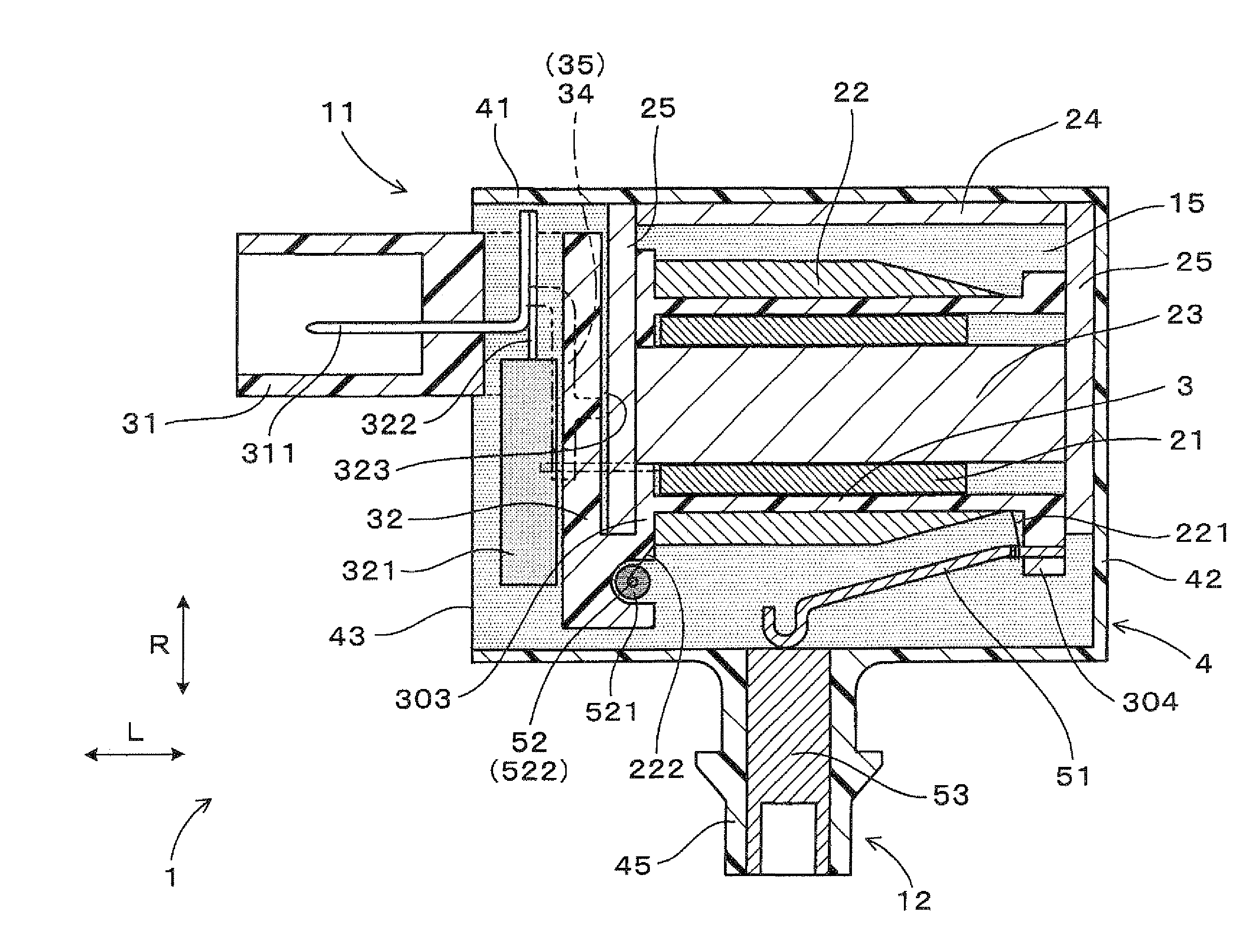
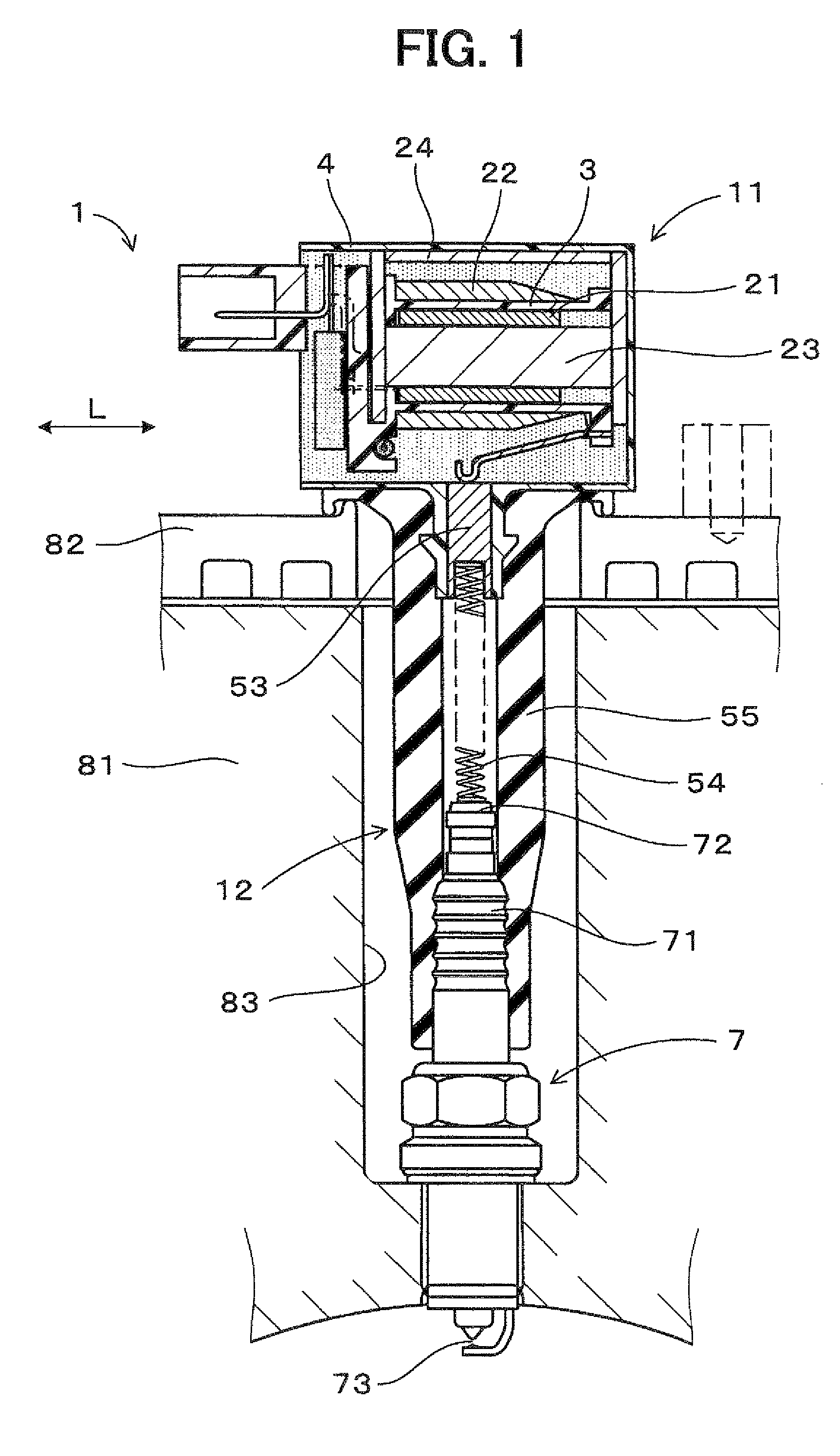
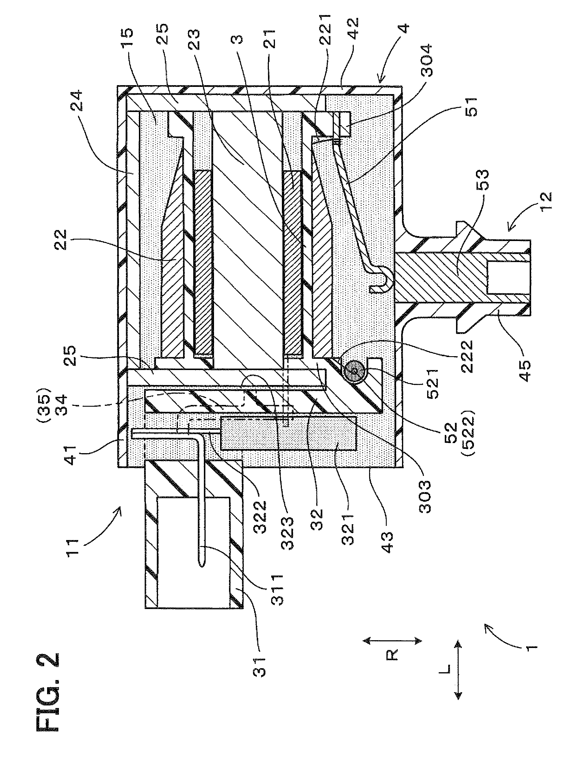
[0025]Now, a typical example of an ignition coil according to an embodiment of the invention will be described below with reference to the accompanying drawings.

[0026]As shown in FIG. 1, an ignition coil 1 of this embodiment includes a coil body 11 for accommodating a primary coil 21 and a secondary coil 22 stacked on the respective inner and outer peripheral sides in a resinous coil case 4. The ignition coil 1 also includes a plug connection portion 12 extending in a direction approximately perpendicular to an axial direction L of the coil body 11 and adapted to bring a high-voltage side winding end 221 of the secondary coil 22 into conduction with a spark plug 7. In the ignition coil 1, the plug connection portion 12 is arranged and inserted into a plug hole 83 provided in a cylinder head 81 and a cylinder head cover 82 of the engine, and the coil body 11 is transversely arranged near an opening of the plug hole 83 in the cylinder head cover 82.

[0027]A...


PUM

PropertyMeasurementUnit
soft magneticaaaaaaaaaa
voltageaaaaaaaaaa
shapeaaaaaaaaaa

Abstract

An ignition coil includes a coil body, a plug connection portion protruding from the coil body, and a connector for electrically connecting the ignition coil to an outside. In the coil body, a primary coil is arranged on an inner peripheral side of a secondary coil, and a center core is arranged on an inner peripheral side of the primary coil. The secondary coil includes a secondary electric wire having thereon an insulating film, wound around an outer periphery of a resinous secondary spool. Furthermore, the connector is formed integrally with an end of the secondary spool in an axial direction.

Description

CROSS REFERENCE TO RELATED APPLICATION[0001]This application is based on Japanese Patent Application No. 2007-200850 filed on Aug. 1, 2007, the contents of which are incorporated herein by reference in its entirety.FIELD OF THE INVENTION[0002]The present invention relates to an ignition coil that can be used for generating sparks between a pair of electrodes in a spark plug for an internal combustion engine, for example.BACKGROUND OF THE INVENTION[0003]In an ignition coil used for an internal combustion engine, a primary coil is wound on a resinous primary spool and a secondary coil is wound on a resinous secondary spool. The primary and secondary coils are accommodated in a resinous coil case to form the ignition coil. The primary coil can be formed in a cylindrical shape using a self-fusing copper wire without the primary spool.[0004]For example, JP-A-8-55742 discloses a coil case of an ignition coil for an internal combustion engine. The coil case is constructed by integrally for...

Claims


Application Information

Patent Timeline
Patent Type & Authority Patents(United States)
IPC IPC(8): H01F27/02
CPCH01F38/12H01F5/04H01F5/02H01F27/40
Inventor AKIMOTO, KATSUNORI
Owner DENSO CORP
Why Eureka
Try Eureka